 Tel:
Tel:  Email:
  WhatsApp:
 Description
Key Technical Specifications
| Parameter | Specification |
|---|---|
| Part Number | WO1G021 / MIF-WO1G021 |
| Module Type | Analog Output |
| Number of Points | 4 Independent Channels |
| Output Signal Range | 4 to 20 mA DC |
| Resolution | 12-bit Binary |
| External Power Supply | 24 VDC (typically loop powered) |
| Load Resistance | Max 600 Ohms (approximate, verify manual) |
| Accuracy | ±0.5% of full scale @ 25°C |
| Conversion Time | < 1 ms per channel |
| Isolation | Channel-to-channel isolation |
| Operating Temp | 0°C to 55°C |
Product Introduction
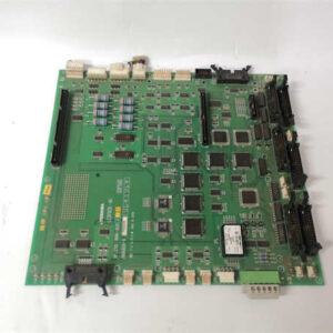
If you are dealing with a Toshiba G3 system in 2026, you are likely fighting a war against time. These systems were workhorses in the 90s and early 2000s, specifically in injection molding and automotive assembly lines. The WO1G021 is the card responsible for talking to your proportional valves or variable speed drives. It’s not fancy, but it is tough. I have seen these modules run for twenty years without a hiccup, sitting next to hot hydraulic presses where they definitely shouldn’t have been installed.The main reason engineers stick with this specific part number is compatibility. You cannot just swap in a newer generic analog card because the backplane pinout on the G3 rack is proprietary. The WO1G021 offers 12-bit resolution, which is standard for that era—enough precision to control a valve position accurately without the noise issues that plague higher-resolution cards in electrically noisy environments. Just be careful with the revision; older versions sometimes had different internal fuse ratings.
Quality SOP & Tech Pitfalls (The Reality Check)
We don’t just pull these off a dusty shelf and ship them. Electronics degrade, especially capacitors in unused inventory. Here is how we verify the WO1G021 before it leaves the shop:
- Visual Inspection: We check the PCB for “green rot” (corrosion) on the solder joints and inspect the ribbon cable connector for bent pins.
- Power-Up Test: We apply 24VDC to the external power terminals to ensure the internal regulation circuitry holds steady.
- Live Loop Test: Using a calibrated signal generator, we force a digital value from the CPU and measure the physical output at the terminals with a Fluke multimeter. We look for the exact 4mA, 12mA, and 20mA points.
- Crosstalk Check: We verify that changing the value on Channel 1 doesn’t cause a voltage spike on Channel 2.
The Engineer’s Warning:
The biggest headache with the WO1G021 isn’t the module itself; it’s the wiring. I once spent four hours troubleshooting a “bad module” at a plastics plant, only to find out the shield grounding on the field cables was corroded. The module was fine. Also, never assume the terminal block is good. The screws strip easily if you use the wrong size screwdriver. And please, for the love of silicon, do not hot-swap this card unless you enjoy blowing output transistors.
Installation & Configuration Guide
Replacing this module requires patience. The G3 racks can be finicky about contact resistance.
- Pre-Installation Safety: Lock out the PLC power. Wait at least 2 minutes for the capacitors to discharge. Take a photo of the existing wiring diagram or the module label.
- Removal: Unscrew the terminal block carefully. Release the locking clip on the side of the module (usually a plastic latch) and slide the unit out. Do not pry it.
- Configuration Check: If your old module has any jumpers or DIP switches on the front face (some revisions do for scaling), copy their positions exactly to the new unit.
- Installation: Slide the new WO1G021 into the slot. Ensure the backplane connector seats flush. Tighten the mounting screws to secure it to the rack.
- Power & Verify: Reconnect the 24VDC power supply. Turn on the PLC. Force an output of 0% (4mA) and 100% (20mA) via the programming software and verify the physical current with a meter at the接线terminals.
Compatible Replacement Models
Since the G3 series is legacy, options are limited.
- ✅ Drop-in Replacement: Toshiba WO1G021 (Different Date Code). Any WO1G021 with the same hardware revision letter will work directly. No reprogramming needed.
- ⚠️ Software Compatible: Toshiba EX Series Analog Modules. Not recommended. While the electrical specs might match, the physical footprint and bus communication protocol are different. This would require rewiring the backplane and rewriting the PLC logic.
- ❌ Hardware Mod Required: Third-party clones. There are some clone manufacturers, but I generally advise against them for critical process control due to reliability issues with the opto-isolators.
Frequently Asked Questions (FAQ)
Q: Can I replace a WO1G021 with a WO1G022?
A: Generally, no. The suffix usually indicates a hardware revision or a slight change in spec (like voltage output vs. current output). Stick to the exact part number unless you have the official Toshiba cross-reference guide.Q: My module shows 20mA even when the PLC commands 0mA. Is it broken?
A: Maybe. First, disconnect the field wiring. If it still reads high, the output transistor is shorted. If it drops to zero when disconnected, you likely have a ground loop or a short in your field cabling.Q: Does this module support 0-10V output?
A: Standard WO1G021 units are typically 4-20mA current output. Some variants might support voltage, but you need to check the specific sub-model number on the nameplate. Don’t guess, or you’ll fry the input impedance.Q: How long is the warranty on these obsolete parts?
A: Since these are surplus, standard warranties are often shorter—usually 30 to 90 days. We test them thoroughly, but vintage electronics carry inherent risks.Q: Do I need to download firmware to this specific module?
A: No. The configuration data is stored in the main CPU memory and sent to the module upon boot. You just need to ensure the I/O table in the CPU matches the physical rack configuration.