
 Tel:
Tel:  Email:
  WhatsApp:
 Description
⚙️ Key Technical Specifications
| Parameter | Specification |
|---|---|
| Module Type | Mixed Digital I/O (Discrete) |
| Input Voltage | 24V DC (Nominal), typically 20.4V – 28.8V |
| Input Current | ~5mA per point (Typical) |
| Input Impedance | 4.7 kΩ (Typical) |
| Output Type | Relay (Form A or Form C contacts) |
| Output Rating | 2A per point @ 240V AC / 30V DC |
| Common Configuration | Independent Commons (Relay isolation) |
| Logic Density | 32 Points (e.g., 16 Inputs / 16 Outputs) |
| Isolation | Opto-isolated Inputs / Relay Isolated Outputs |
| Response Time | < 1ms (Input), < 10ms (Output mechanical) |
| Power Consumption | ~0.15A @ 5V DC (Internal Logic) |
| Dimensions | Standard G7 Slot Width (approx. 30mm-50mm wide) |
🔍 Product Introduction
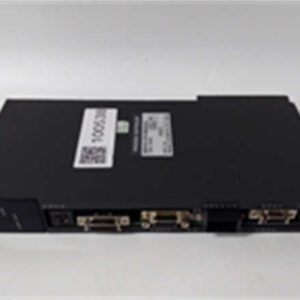
When you are staring at a wall of relays in a cabinet that hasn’t been touched since the Clinton administration, finding space for new controls is a nightmare. The Toshiba LBIW01G021 is the kind of “hybrid” module that saves you rack space. Instead of buying one card for inputs and another for outputs, this unit splits the difference, giving you a mix of both in a single footprint.I’ve used these G7 modules in water treatment plants where reliability matters more than fancy graphics. The beauty of this specific part is the relay output. Unlike transistor outputs that fry if you sneeze a voltage spike at them, relays are electrically isolated and can switch AC or DC loads without needing complex wiring changes. It’s a brute-force solution: read a float switch (24V input) and trip a contactor (Relay output) with zero electrical noise bleeding between the two sides. If you’re keeping an aging Toshiba system alive, this is the Swiss Army Knife of the chassis.
🏭 Application Scenarios & Field Case Study
Common Use Cases:
- Material Handling: Reading limit switches (Inputs) and firing conveyor contactors (Outputs).
- Pump Stations: Monitoring “Running” and “Fault” dry contacts from VFDs and controlling start/stop commands.
- Packaging Machinery: Interfacing with photo-eyes and solenoid valves.
- Legacy Retrofits: Replacing failed external relay banks by moving logic into the PLC.
Field Failure Story (Automotive Assembly Line):
We had a robotic weld cell that was throwing random “Safety Gate Open” faults, but the gate was clearly closed. The maintenance team blamed the sensors. I traced the wiring back to the PLC and found the common ground on the old input section of the hybrid card had lifted due to thermal cycling. Since the LBIW01G021 combines inputs and outputs, the vibration from the nearby punch press had fatigued the solder joints. I swapped in a fresh unit, secured the DIN rail mounting screws tighter to dampen vibration, and the ghost fault vanished.
🛠️ Quality SOP & Tech Pitfalls
The Lab Report (SOP):
We verify functionality before it leaves the bench.
- Visual Inspection: We check the green terminal blocks for cracks and ensure the locking clips on the side aren’t broken (a common issue with older plastic).
- Backplane Check: We inspect the gold bus connectors on the rear to ensure they are flush and not recessed, which causes “ghost” errors.
- Live Point Test: We toggle a 24V source on the inputs and verify the LED illuminates. We then force the outputs via software and listen for the distinct click of the relay closing.
- Continuity: We use a multimeter to ensure the relay contacts close cleanly with near-zero resistance.
The Engineer’s Warning (Pitfalls):
- The “Mixed” Confusion: Don’t assume all terminals are the same. This module has specific rows for Inputs and specific rows for Outputs. If you wire a 120V AC light directly onto an Input terminal because you didn’t check the pinout diagram, you will let the magic smoke out.
- Relay Life: Remember, these are mechanical relays. If you use them to switch a high-inrush solenoid valve rapidly (like 10 times a second), the contacts will weld shut eventually. For fast switching, use a transistor output module; keep this one for slower, heavier loads.
🔧 Installation & Configuration Guide
This is a straightforward swap, but attention to detail prevents magic smoke.
- Pre-Installation (Safety First):
- ⚠️ Lockout/Tagout: Kill power to the PLC rack.
- Labeling: Label every single wire. The terminal blocks on these mixed modules can be dense, and losing track of Wire #104 vs #105 is a headache you don’t need.
- Removal:
- Unplug the terminal block(s). On some G7 models, the block is shared; on others, it’s split top/bottom. Be gentle.
- Release the locking clip at the bottom of the module and slide it out.
- Installation:
- Seat the Module: Slide the LBIW01G021 into the empty slot. Ensure it clicks firmly onto the backplane bus.
- Re-Wire: Plug your terminal blocks back in. Double-check that Input wires go to Input terminals (usually labeled X) and Output wires go to Output terminals (usually labeled Y).
- Power-On & Testing:
- Restore power.
- Monitor the LED status lights. Force an output in the program to ensure the relay clicks. Toggle a physical switch to verify the input LED lights up.
🔄 Compatible Replacement Models
| Model Number | Compatibility | Notes |
|---|---|---|
| ✅ Toshiba LBIW01G021 | Direct Drop-In | Exact match. Verify I/O count (16in/16out) matches your application. |
| ⚠️ Toshiba LBIR1G | Hardware Compatible | Likely a pure Relay Output module. You would lose your inputs if you use this. Only use if you rewire. |
| ❌ Generic Clone | Incompatible | Proprietary bus protocol. A generic “relay module” will not talk to the Toshiba CPU. |
❓ Frequently Asked Questions (FAQ)
Q: Can I hot-swap this module?
A: Technically the G7 series allows it, but I never risk it with relay cards. The inductive kickback from the relay coil when you pull the card can arc the backplane pins. Take the 2 minutes to power down.Q: My outputs aren’t working, but the LEDs are on.
A: If the LED is on but the relay doesn’t click, the internal driver might be fried. If the relay clicks but the device doesn’t run, check your external fuse or the wiring on the terminal block. Also, ensure you have voltage on the “Common” terminals for the outputs.Q: What is the maximum wire size this accepts?
A: The terminal blocks usually accept up to 14 AWG (2.0 mm²), sometimes 12 AWG if you really struggle with it. Stick to 14-16 AWG for the most reliable connection.Q: Does this require any configuration in the software?
A: No. Unlike analog cards, digital I/O is plug-and-play. The CPU sees it as X and Y addresses based on the slot number. Just make sure your logic addresses match the physical slot location.Q: Is the terminal block included?
A: Yes, our surplus units come with the terminal block attached. Some vendors sell the card and block separately, which is a pain, but ours are complete ready-to-install units.