 Tel:
Tel:  Email:
  WhatsApp:
 Description
Key Technical Specifications
| Parameter | Specification | Notes |
|---|---|---|
| Input Voltage | 200V – 240V AC | Single or Three Phase |
| Rated Output | 0.1 kW (approx.) | Very low power application |
| Output Current | ~0.75 A – 0.9 A | Check specific motor nameplate |
| Control Method | V/f Control | Basic scalar control |
| Frequency Range | 0.5Hz – 400Hz | Programmable limits |
| Cooling | Natural Convection / Small Fan | No heavy-duty heatsink |
| Protection | IP20 | Indoor use only |
| Braking | Built-in Braking Resistor | Often included in this size |
| Dimensions | Ultra-Compact | Designed for tight spaces |
Product Introduction
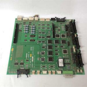
This is what we call a “fractional horse” drive, but it’s usually the one that stops the whole line when it dies. The Toshiba FDCW01G001 is part of the VF-S15 family—Toshiba’s answer to compact, cost-effective motor control. You’ll find these driving tiny conveyor belts on packaging machines, little agitators in chemical dosing skids, or exhaust fans where space is non-existent.It’s rated for about 0.1kW (roughly 1/8th of a horsepower). That sounds small, but in the world of automation, this thing punches above its weight. It handles 200V input and gives you vector control capability, meaning it can actually hold a speed fairly well even if the load changes slightly. The “FDCW” prefix usually indicates a specific form factor designed for panel builders who need to cram 20 drives into a cabinet the size of a shoebox. It’s simple, rugged, and if you don’t force it to overheat, it will outlive the machine it’s attached to.
Quality SOP & Tech Pitfalls (The Reality Check)
The Lab Report (SOP)
Small drives get abused more than big ones because people treat them like toys. Here is how we check them:
- Visual Inspection: We look at the terminal blocks. On these small units, the plastic melts easily if someone overtightened the screws.
- Capacitor Health: Since this is likely an older unit, we check the DC bus capacitors for leakage. If they are bulging, the drive is trash.
- IGBT Test: We use a multimeter in diode mode to check the output transistors (U, V, W) against the DC bus (+/-). If any read shorted, the module is dead.
- Live Test: We hook up a small 0.1kW test motor and ramp it up to 60Hz. We listen for the “whine”—if it sounds like a dying mosquito, the PWM carrier frequency is off or the IGBTs are degrading.
The Engineer’s Warning (Pitfalls)
- The “Single Phase” Trap: This drive can take single-phase input, which is great. But if you feed it single-phase 240V and try to pull the full rated current, the rectifier diodes will overheat. You generally have to derate the drive by 30% when running on single phase. If you ignore this, you’ll smell burnt electronics within an hour.
- Terminal Torque: These terminals are tiny. I’ve seen technicians strip the threads trying to torque them down with a wrench. Use a small flathead screwdriver and gentle pressure. If you strip the terminal, you have to replace the whole unit.
- Cooling: Some of these micro-drives rely on natural convection (no fan). If you mount it flat against a wall or stack other drives right next to it without spacing, it will trip on thermal overload (OH) constantly. Give it breathing room.
Installation & Configuration Guide
Phase 1: Pre-Installation
- Safety First: Lockout/Tagout. Wait 5 minutes for capacitors to discharge (LED on front should go dark).
- Verify Power: Confirm you have 200-240V. Do not put 480V on this; it will explode.
- Check Motor: Ensure your motor is roughly 0.1kW. If you hook this up to a 1kW motor, the drive will just trip on Overcurrent (OC).
Phase 2: Removal
- Label Wires: Mark R/L1, S/L2 (Input) and U, V, W (Output).
- Unclip: Release the DIN rail clip at the bottom.
Phase 3: Installation
- Mount: Snap onto DIN rail.
- Wire: Connect power and motor. Keep wires away from the front face if possible to avoid noise interference.
- Ground: Connect the ground terminal (E/G) to your panel earth. Critical for noise reduction.
Phase 4: Power-On & Testing
- Keypad: Plug in the remote keypad (if separate).
- Parameter Check: Verify parameter F03 (Motor Rated Current) matches your motor nameplate.
- Jog: Hit the “Run” button. Check rotation direction.
Compatible Replacement Models
| Compatibility Tier | Model Number | Differences & Notes |
|---|---|---|
| ✅ Direct Replacement | VF-S15 (VFS15-2004PL) | The standard commercial version. Same specs, widely available. |
| ⚠️ Software Compatible | VF-AS1 (Mini) | Newer series. Better performance, but parameter codes are different. Requires reprogramming. |
| ❌ Hardware Mod Required | NC3 Series | Older legacy unit. Different mounting holes and terminal layout. Avoid unless necessary. |
Frequently Asked Questions (FAQ)
Q: Can I use this on a 120V circuit?
A: No. The model number suffix “01” typically denotes the 200V class. If you need 120V input, you need a model ending in “00” (e.g., FDCW00…). Putting 120V into a 200V drive won’t break it, but the motor won’t spin properly, and you’ll get undervoltage faults.Q: My drive shows “OL1”. What did I do wrong?
A: That’s “Overload 1.” You are asking the motor to do too much work, or the acceleration time is too fast. Check if the conveyor belt is jammed. If it’s clear, increase the Acceleration Time parameter (F7).Q: Does this have a built-in brake resistor?
A: Most units in the “FDCW” series under 0.4kW have a built-in braking resistor. You can verify this by checking the manual for your specific serial number, but generally, you don’t need an external box for light loads.Q: The display is flashing “LU”. What does that mean?
A: Low Voltage. Your input power has dropped below the threshold (usually around 170V). Check your main breaker or transformer tap. If the power is stable, the internal smoothing capacitors might be dried out and need replacing.Q: Can I control the speed with a 0-10V signal from my PLC?
A: Yes. Connect your 0-10V signal to the VI (Voltage Input) and GND terminals. You may need to change a jumper or parameter (CNOD) to select “Voltage Input” mode instead of “Current Input” (4-20mA).