 Tel:
Tel:  Email:
  WhatsApp:
 Description
⚙️ Key Technical Specifications
| Parameter | Specification |
|---|---|
| Module Type | Analog Input & Output Mixed / Combo |
| Input Signal Range | 4-20mA DC, 1-5V DC (Software selectable) |
| Output Signal Range | 4-20mA DC (Sinking/Sourcing capable) |
| Resolution | 12-bit or 16-bit (Depending on firmware revision) |
| Conversion Speed | < 1ms per channel (Typical) |
| Isolation | Channel-to-Channel and Bus Isolation (Optocoupler) |
| Input Impedance | 250 Ω (for 4-20mA loop) |
| Max Load Resistance | 600 Ω (Typical for output side) |
| Accuracy | ±0.1% of Full Scale @ 25°C |
| Operating Temperature | 0°C to 60°C (32°F to 140°F) |
| Power Consumption | ~0.3A @ 5V DC (Internal Logic) |
| Dimensions | Standard G7 Slot Width (approx. 30mm-50mm wide) |
🔍 Product Introduction
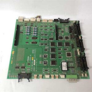
Finding parts for older Toshiba G7 systems can feel like hunting for a needle in a haystack, but the Toshiba AICWO1G022 is one of those cards you want to have in your spares cabinet when the phone rings at 3 AM. This isn’t a fancy new Ethernet-enabled remote IO block; it’s a rugged, old-school workhorse designed to sit in a hot rack and convert current loops without complaining.I’ve deployed these in wastewater treatment plants where the electrical noise from variable frequency drives would make sensitive modern gear cry. The internal isolation on this module is solid—it keeps the noisy ground loops off the backplane and protects your expensive CPU. If you are running a legacy paper mill or a power plant that hasn’t been upgraded since the late 90s, this module is the glue holding your PID loops together. It’s simple, it’s durable, and frankly, they don’t build them quite this heavy anymore.
🏭 Application Scenarios & Field Case Study
Common Use Cases:
- Water Treatment: Monitoring flow rates via magnetic flow meters (4-20mA input) and controlling chemical dosing pumps (4-20mA output).
- HVAC Systems: Reading duct pressure sensors and modulating damper actuators in large commercial units.
- Manufacturing: Hydraulic pressure monitoring on injection molding machines.
- Power Plants: Feedwater level indication and control valve positioning.
Field Failure Story (Midwest Paper Mill):
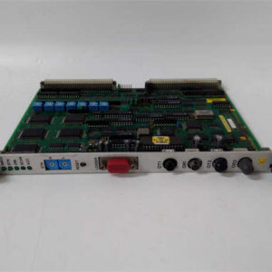
We had a persistent issue on a stock preparation line where the consistency transmitter was reading erratic values. The operator thought the sensor was clogged. I checked the wiring, which was fine, but the value on the HMI was still dancing around. I swapped out the old Toshiba analog card with a spare AICWO1G022. The key here was checking the DIP switches on the front of the new card—they were set to voltage mode by default. Once I flipped them to current mode (4-20mA), the reading stabilized instantly. The old card had a failing ADC that was drifting with temperature changes.
🛠️ Quality SOP & Tech Pitfalls
The Lab Report (SOP):
We don’t just ship cardboard boxes.
- Visual Inspection: We check the terminal block screws for stripping—evidence of previous rough installation—and ensure the PCB tracks are clean.
- Backplane Continuity: We verify the gold pins on the rear connector aren’t bent or recessed, which causes “ghost” faults in the rack.
- Live Loop Test: We hook up a precision calibrator to inject a known 4mA and 20mA signal, then read the digital value in the PLC to ensure linearity.
- Packaging: Wrapped in anti-static foam and boxed with desiccant to prevent corrosion during transit.
The Engineer’s Warning (Pitfalls):
- The DIP Switch Trap: This module usually has tiny DIP switches or jumpers on the front or side to select Voltage vs. Current mode. Do not ignore these. If your sensor outputs 4-20mA but the switch is set to 1-5V, you’ll see weird readings or nothing at all.
- Ground Loops: Even though it’s isolated, if you daisy-chain the power supply incorrectly, you can introduce hum. Keep your analog commons separate from your digital commons.
🔧 Installation & Configuration Guide
Swapping this card is straightforward if you respect the electronics.
- Pre-Installation (Safety First):
- ⚠️ Power Down: While some PLCs support hot-swapping, analog cards are sensitive. I always recommend killing the rack power to avoid arcing the backplane pins.
- Document Settings: Look at the old card. Write down the position of every single DIP switch. Take a photo with your phone.
- Removal:
- Unscrew the terminal block (or release the locking mechanism if it’s a spring clamp type).
- Pull the card straight out. Don’t wiggle it too much; you don’t want to stress the motherboard connection.
- Installation:
- Set Switches: Configure the DIP switches on the AICWO1G022 to match your old unit before you slide it into the slot.
- Seat the Card: Slide it in firmly until the connector mates. Tighten the mounting screws to secure it against vibration.
- Wire Up: Reconnect your field wires. Check polarity carefully (+/-).
- Power-On & Testing:
- Restore power.
- Force a 4mA signal from the field (or use a simulator) and verify the raw integer value in the PLC logic matches expectations (e.g., 6400 counts for 4mA).
🔄 Compatible Replacement Models
| Model Number | Compatibility | Notes |
|---|---|---|
| ✅ Toshiba AICWO1G022 | Direct Drop-In | Exact hardware match. Verify DIP switch settings. |
| ⚠️ Toshiba AICW1G | Hardware Compatible | Likely an input-only version. You will lose the output capability if you substitute this. Check the manual. |
| ❌ Third-Party Generic | Incompatible | Proprietary bus architecture. You cannot use a generic “Modbus Analog Module” here without rewiring the whole cabinet. |
❓ Frequently Asked Questions (FAQ)
Q: Can I swap this while the PLC is running?
A: You can, but I wouldn’t risk it. Analog modules draw power from the backplane, and yanking them live can cause a voltage dip that might crash the CPU or corrupt the program. Take the 5 minutes to shut down.Q: My reading is negative. What did I do wrong?
A: Check your wiring polarity first. Analog signals are polarized. If that’s good, check the DIP switch configuration—if it’s set for bipolar (-10V to +10V) but you’re feeding it unipolar (0-10V), it might interpret the scale differently depending on the offset.Q: Does this support thermocouples?
A: No. This specific model (AICWO1G022) is designed for voltage and current loops (mV/V/mA). If you need to read a thermocouple (Type J/K/T), you need a dedicated temperature input module, usually labeled “THC” or similar in the Toshiba catalog.Q: How many channels does this have?
A: It typically features a mix of inputs and outputs (often 4 inputs and 2 outputs, or similar density). Check the terminal labeling on the faceplate to confirm the exact point count for your logic addressing.Q: Is the software compatible with newer Toshiba CPUs?
A: Generally, yes. The G7 series is backward compatible with many EX series CPUs, but you should verify the “I/O Allocation” in your programming software (ProLink or TOSLINE) to ensure the new CPU recognizes the analog points correctly.