 Tel:
Tel:  Email:
  WhatsApp:
 Description
Key Technical Specifications
| Parameter | Specification |
|---|---|
| Manufacturer | Toshiba Machine (Toshiba) |
| Module Type | 2-Axis Servo Control Module |
| Series | HCS1000 |
| Axes | 2 axes (X and Y/Z) |
| Input Voltage | 100V AC (Typical for HCS1000) |
| Mounting | DIN-rail (Standard IEC 60715) |
| Dimensions | 120mm (W) x 100mm (H) x 75mm (D) |
| Communication | Toshiba HCS1000 PLC (via I/O Link) |
| Pulse Output | High-speed pulse output for servo drives |
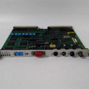
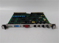
Product Introduction
The Toshiba HC422B is a motion control module designed for the HCS1000 series of programmable logic controllers (PLCs). It provides the necessary interface to control up to 2-axis servo motors, making it a critical component for applications requiring precise positioning, such as pick-and-place machines, conveyors, and small automation lines.Featuring high-speed pulse output capabilities, this module sends command signals to servo drives to control motor speed and position. It operates on 100V AC power and connects directly to the HCS1000 PLC via the I/O link network. The module is DIN-rail mountable, ensuring a secure and organized installation within an industrial control panel.
Installation & Configuration Guide
Preparation (10 min)
- Power Down: Turn off the main power supply to the control panel. Use a voltage tester to confirm no live circuits are present.
- Mounting Rail: Ensure the DIN rail in the control panel is clean and free of debris. The HC422B uses standard IEC 60715 mounting clips.
- ESD Protection: If working in a dry environment, wear an anti-static wrist strap connected to a grounded point to prevent damage to the module’s electronics.
Removal (5–10 min)
- Cable Disconnection: Loosen the terminal screws on the front of the module. Carefully disconnect the wiring (servo outputs and power) to prevent strain on the solder joints.
- Release Latch: Press the release latch on the side of the module (if equipped) or gently pry it off the rail using a flat-head screwdriver.
- Storage: Place the removed module in an anti-static bag for storage or transport.
Installation (10 min)
- Align: Slide the module onto the DIN rail. Ensure the mounting clips engage securely with the rail.
- Lock: Press down firmly until you hear a distinct “click,” indicating the module is locked in place.
- Wiring: Connect the wires to the terminal block.
- Axis 1/2: Servo motor control outputs (Pulse/Direction or CW/CCW).
- L+/N: 100V AC power supply.
- Shield: Connect the cable shield to the grounding terminal if using shielded cables.
Power-On & Test (10 min)
- Visual Check: Inspect the front panel for any physical damage or loose connections.
- Power Up: Restore power to the control panel.
- LED Indicators: Monitor the status LEDs:
- RUN/ALM: Green indicates normal operation; red indicates a fault (e.g., overvoltage or wiring error).
- Axis 1/2: Blinking indicates active pulse output.
- PLC Configuration: Verify the PLC recognizes the module on the network and that the servo motors respond to position commands.
Troubleshooting Quick Reference
| Symptom | Probable Cause | Corrective Action |
|---|---|---|
| ALM Light ON | Overvoltage or wiring error | Check the 100V AC power supply voltage. Ensure no wires are touching adjacent terminals. |
| No Motor Movement | Incorrect PLC program | Verify the PLC program is sending the correct pulse and direction commands. |
| Intermittent Movement | Electrical noise | Use shielded cables and ensure the shield is grounded at both ends. Install ferrite chokes on the output wires. |
| Communication Error | PLC network issue | Verify the I/O link cable is securely connected. Check the PLC’s network settings and module address. |
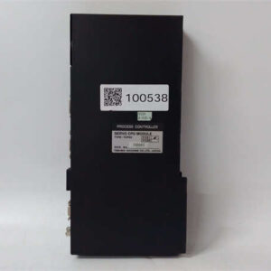
Dimensions, Mounting & Wiring Notes
- Form Factor: DIN-rail mountable (Standard IEC 60715)
- Dimensions: 120mm (Width) x 100mm (Height) x 75mm (Depth)
- Mounting: Secure the module to a 35mm DIN rail using the side clips. Do not overtighten the terminal screws; use 0.5 N·m torque.
- Wiring Notes: The output terminals send high-speed pulse signals to servo drives. Ensure the source/sink configuration matches the module’s internal settings (set via DIP switches or PLC parameter).
HC422B TOSHIBA
FAQ
Can I use the HC422B with a different Toshiba PLC series?
This module is specifically designed for the HCS1000 series of Toshiba PLCs. It uses the HCS I/O link network. It is not compatible with other series like the 70/100H or larger PLCs without an interface module.What is the maximum pulse output frequency?
The HC422B can output pulses at a rate of up to 100 kHz per axis, depending on the specific motion profile and the capabilities of the connected servo drives.Do I need to set DIP switches on the module?
Yes, the HC422B typically requires DIP switch settings to define the pulse output mode (e.g., 1-phase vs 2-phase) and the direction signal type. These settings must match the configuration of the connected servo drives.Is this module hot-swappable?
No, the HC422B is not hot-swappable. You must power down the entire control system before removing or inserting this module to prevent damage to the PLC or the module itself.What is the difference between the HC422B and the HC422A?
The primary difference is the input voltage and the specific drive interface. The “-B” version typically supports 100V AC input and is used with a specific line of Toshiba servo drives, while the “-A” version may be for 24V DC or a different drive series. The “-B” is generally used for higher power applications.
Toshiba HC422B Motion Control Module