 Tel:
 Email:
 WhatsApp:
Description
Key Technical Specifications
| Parameter | Specification |
|---|---|
| Product Type | Contact input terminal board (TBCI-H1) |
| Model | IS200TBCIH1BBC |
| System Platform | GE Speedtronic Mark VI |
| Primary Role | Dry-contact input termination and signal conditioning |
| Terminal Blocks | 2 × barrier terminal blocks, TB1 and TB2 |
| Total Terminals | Multiple terminals across both blocks |
| Input Type | Dry-contact inputs |
| Nominal Excitation | 125 VDC floating supply for TBCIH1 boards |
| Input Filter | Hardware filter per channel |
| Mounting | Mark VI VME I/O rack |
| Connectors | Multiple board-edge/backplane connectors; verify with OEM drawing |
| Protection | MOV/surge and high-frequency noise suppression at input points |
Product Introduction
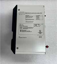
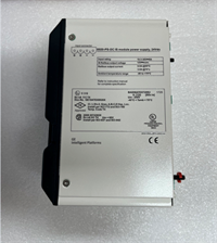
The IS200TBCIH1BBC is one of those boards that looks boring until it kills your startup. It is a GE Speedtronic Mark VI contact input terminal board, used to bring field switch contacts into the VME I/O rack for gas and steam turbine control. It does not run control logic by itself. It sits in front of the processor board, handles the messy field wiring, and passes conditioned contact status back into the rack.Engineers keep this board in the spare cabinet because turbine trips do not wait for procurement. The dual terminal blocks, input filtering, and surge suppression at each input point are the real value. I have seen a single oxidized terminal or wrong excitation assumption create hours of false diagnostics. The BBC suffix matters. Do not treat it as generic “IS200TBCIH1.”
Quality SOP & Tech Pitfalls
The Lab Report (SOP)
- Visual and counterfeit check: full model IS200TBCIH1BBC, PCB revision, terminal block condition, connector pins, burn marks.
- Connector inspection: JR/JS/JT-style backplane connectors checked for bent pins and corrosion.
- Multimeter checks: terminal continuity, isolation between groups, MOV/suppression components visually verified.
- Insulation resistance: spot-check input groups to chassis/ground per safe bench practice.
- Rack-level verification: if a Mark VI VME rack and matching processor board are available, verify channel mapping and contact status reporting.
- Documentation: record PCB revision, connector layout, and photos before anti-static sealing.
The Engineer’s Warning (Pitfalls)
- Mixing TBCIH1 and TBCIH2 is a classic mistake. TBCIH1 boards are typically tied to 125 VDC excitation; TBCIH2 boards are typically tied to 24 VDC excitation. Wrong excitation means no valid input reading, or worse, damaged field wiring.
- Do not assume “same terminal number = same channel.” The Mark VI I/O map is defined by the processor board, cable harness, and cabinet drawing. I once watched a crew swap a terminal board, trust the printed numbers, and spend half a shift chasing a phantom trip because the channel mapping did not match the original harness.
- ESD and connector damage are silent killers. These boards are electrostatic sensitive, and the backplane connectors do not forgive rough handling.
Installation & Configuration Guide
1. Pre-Installation ️
- Follow plant safety procedures and obtain clearance before working on turbine control I/O.
- Remove rack power and allow capacitors to discharge.
- Photograph every wire on TB1/TB2, every backplane connector, and the original board label.
- Record the processor board model, cable part numbers, and I/O configuration.
2. Removal
- Label each wire before disconnecting.
- Release backplane connectors carefully; do not pry the board out by the terminal blocks.
- Inspect the old board for burnt terminals, corroded pins, or cracked MOV components.
3. Installation
- Copy all original settings before installing the replacement. This board family typically has no user DIP switches, but jumper positions, connector assignments, and terminal wiring must match exactly.
- Seat the board fully into the VME rack.
- Reconnect TB1/TB2 wiring exactly per the original photos and cabinet drawing.
- Reinstall backplane connectors and verify locking hardware.
4. Power-On & Testing
- Restore rack power and check for abnormal LEDs or alarms.
- Verify each dry-contact input against the I/O map.
- Confirm input filtering behavior and contact bounce handling through the processor diagnostics.
- Document the replacement, including PCB revision and terminal photos.
Compatible Replacement Models
| Compatibility | Model | Notes |
|---|---|---|
| Drop-in Replacement | IS200TBCIH1BBC | Same Mark VI TBCIH1 terminal board; verify BBC suffix and PCB revision. |
| ️ Software/Configuration Compatible | IS200TBCIH1Bxx variants | Same TBCIH1 family may fit, but terminal mapping, revision, and excitation must be confirmed against the OEM drawing. |
| Hardware Mod Required | IS200TBCIH2BBC / Mark VIe boards | Mark VIe terminal boards are not direct replacements for Mark VI TBCIH1 boards. Migration requires engineering review, rewiring, and configuration changes. |
Frequently Asked Questions (FAQ)
Q: Is the IS200TBCIH1BBC a PLC or controller?
No. It is a contact input terminal board for the Mark VI system. It terminates field wiring and conditions signals for the VME I/O processor.Q: Can I replace IS200TBCIH1BBC with IS200TBCIH2BBC?
Not as a direct swap. TBCIH1 and TBCIH2 belong to different excitation families and platform generations. TBCIH1 is typically 125 VDC; TBCIH2 is typically 24 VDC and associated with Mark VIe.Q: Does this board have DIP switches?
Typically no. This terminal board family is generally configured by wiring, backplane connectors, and system software rather than user DIP switches. Still photograph the original board before removal.Q: What causes false contact readings after replacement?
Usually wrong wiring, wrong excitation voltage, damaged backplane connectors, or a mismatched I/O map. The terminal numbers on the board are not enough.Q: Can it be tested on a bench without a Mark VI rack?
Only partially. You can check continuity, insulation, connector integrity, and visual condition. Full channel validation requires the correct processor board and rack.Q: Is this board still in production?
Mark VI is a legacy platform. Most units in circulation are surplus, removed, or refurbished. Verify condition, revision, and return policy before buying.