
 Tel:
Tel:  Email:
  WhatsApp:
 Description
Key Technical Specifications
| Parameter | Specification |
|---|---|
| Input Voltage | 24 VDC (Nominal) |
| Communication Bus | ISBus (Proprietary GE Protocol) |
| Interface Type | Fiber Optic & RS-232C |
| Mounting Style | DIN Rail / Backplane Mount |
| Module Height | 3U (Standard Eurocard) |
| Operating Temp | -20°C to +70°C |
| Signal Inputs | Generator Field Voltage/Current |
| Data Rate | 1200 to 38.4 kBaud |
| Dimensions | Approx. 17.8 cm x 33.0 cm |
| Weight | ~0.95 kg |
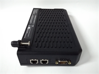
Product Introduction
The GE IS200EISBH1A is a specialized communication interface board designed for the EX2100 excitation control system and Mark V turbine controls. It serves as a critical bridge, managing data transmission between the M1, M2, and C controllers via the proprietary ISBus. This module ensures that voltage and current feedback from the generator field is accurately relayed to the DSPX controller for processing.In operational environments, this board handles high-speed signal conversion. It accepts fiber optic inputs from the generator field and routes them through the control backplane. A key differentiator is its support for redundant exciters, allowing for stable operation even if a primary path fails. The inclusion of an RS-232C port facilitates direct connection to operator terminals for diagnostics without disrupting the main control loop.
Installation & Configuration Guide
Preparation (10 min)
Ensure the exciter system is fully de-energized. Verify that the LED indicators on the EPDM and EPSM power supplies are off. Gather necessary tools: anti-static wrist strap, fiber optic cleaning kit, and a small flathead screwdriver. Static discharge can destroy the sensitive DSPX interface circuitry.Removal (5–10 min)
Open the control cabinet door. Locate the DSPX board; the EISB module is mounted directly beneath it.
- Disconnect all fiber optic cables from the front panel. Label them immediately (e.g., “Field Voltage,” “Exciter Current”) to prevent cross-wiring later.
- Loosen the captive screws at the top of the DSPX panel and the bottom of the EISB panel.
- Pull the ejector tabs upward gently to disengage the boards from the backplane connectors. Remove the assembly carefully.
Installation (10 min)
Separate the old EISB from the DSPX if replacing only the communication board. Insert the replacement IS200EISBH1A into the slot below the DSPX. Align the guides and push firmly until the backplane connector seats fully. Tighten the panel screws in an alternating pattern to ensure even pressure. Do not overtighten; the goal is secure contact, not crushing the PCB.Power-On & Test (10 min)
Reconnect the labeled fiber optic cables to their respective ports. Restore power to the control rack. Observe the system startup sequence. Use the RS-232 tool port to verify communication handshake with the controller. Check for “ISBus Error” alarms in the diagnostic log.
Troubleshooting Quick Reference
| Symptom | Probable Cause | Corrective Action |
|---|---|---|
| No Comm with DSPX | Backplane connection loose | Reseat the board; check for bent pins on the DIN connector. |
| Fiber Link Down | Dirty optical connectors | Clean fiber tips with isopropyl alcohol and lint-free wipes. |
| Redundancy Fault | Mismatched firmware | Verify revision codes (e.g., AAB) match across redundant units. |
| RS-232 Timeout | Baud rate mismatch | Ensure terminal settings match the card’s dip switch (default often 38.4k). |
Dimensions, Mounting & Wiring Notes
- Form Factor: Standard 3U height module.
- Mounting: The board plugs directly into the control rack backplane. It does not use individual DIN rails but mounts as part of the DSPX/EISB stack.
- Wiring: Connections are primarily via fiber optic LC or ST connectors (depending on specific revision) located on the faceplate.
- Power: Derived from the backplane (24VDC), requiring no external wiring harnesses for standard operation.
FAQ
Q: Can I use this board in a Mark VI system?
A: Generally, no. This board is designed for the EX2100 and Mark V architectures. While physically similar, the firmware and bus protocols for Mark VI are different. Stick to Mark V or EX2100 replacements.Q: What does the “AAB” suffix mean in IS200EISBH1AAB?
A: The suffix indicates the revision level. “AAB” typically implies a specific hardware update or component change. For redundancy, both cards in a pair should ideally have the same suffix to avoid compatibility glitches.Q: Does this come with the fiber optic cables?
A: No. As a replacement component, the unit usually ships as a standalone module. You will reuse your existing fiber cables—make sure you inspected and cleaned them before plugging them into the new card.Q: How do I know if my card is actually bad?
A: If you see persistent “ISBus Comm Fail” alarms and reseating the card doesn’t help, try swapping it with a known good spare from a non-critical rack. Also, check the 24VDC supply rail; low voltage can cause communication dropouts that look like board failures.Q: Is this sold as new or refurbished?
A: Since GE has discontinued this line, “New Original” stock is extremely rare. Most available units are Refurbished or New Surplus. We test all refurbished units on a dedicated EX2100 test bench to verify signal integrity before shipping.