 Tel:
Tel:  Email:
  WhatsApp:
 Description
⚙️ Key Technical Specifications
| Parameter | Specification |
|---|---|
| Manufacturer | General Electric (GE) |
| Part Number | IS200EMCSG1A |
| Product Type | Exciter Multi-Bridge Conduction Sensor Board |
| Application | EX2100 Excitation Control System |
| Input Signal | SCR Gate Pulse / Voltage Drop Sensing |
| Interface | DB9 Serial Interface (Controller Link) |
| Mounting | DIN Rail / Chassis Mount (Exciter Aux Cabinet) |
| Dimensions | Approx. 260 × 60 × 30 mm |
| Weight | 0.45 kg |
| Operating Temp | -20°C to 65°C |
| Revision | Version A (Standard Production Model) |
📝 Product Introduction
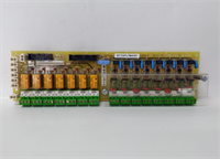
The IS200EMCSG1A is a specialized sensor board used within the GE EX2100 excitation control system to monitor the health and firing status of power thyristors (SCRs). It acts as the “eyes” of the exciter power bridge, detecting whether each SCR is conducting properly during its assigned cycle. This data is critical for the main controller to determine if a fuse has blown or if a thyristor has failed short/open, preventing generator field failure.This module is distinct from standard I/O boards because it handles high-speed pulse monitoring rather than simple analog voltage measurement. It connects directly to the Exciter Backplane (EBKP) and communicates via a dedicated serial link. Field technicians often identify this board by its specific DB9 connector layout, which carries the aggregated conduction status from the power cabinet to the logic solver. Without this board, the system cannot detect “dropout” events in the rectifier bridges.
🔧 Installation & Configuration Guide
Preparation (10 min)
- Safety First: De-energize the EX2100 system and apply Lockout/Tagout (LOTO). High voltage is present on the power buses.
- ESD Protection: Wear a grounded wrist strap. The internal circuitry is sensitive to static discharge.
- Verify Hardware: Ensure you have the correct revision (IS200EMCSG1A). Check the EBKP backplane compatibility (e.g., IS200EBKPG1B).
Removal (5–10 min)
- Locate the EMCS board in the exciter auxiliary cabinet.
- Disconnect the DB9 communication cable carefully. Do not pull on the wire harness.
- Release the mounting clips or DIN rail latch. Slide the board out gently to avoid damaging adjacent wiring.
Installation (10 min)
- Insert the IS200EMCSG1A into the mounting slot. Secure it firmly; vibration can cause connection failures in industrial environments.
- Reconnect the DB9 cable to the appropriate port. Tighten the jackscrews to ensure a solid ground reference for the signal.
- Verify that the input sensing wires (from the SCRs/fuses) are connected to the terminal block (if applicable to your specific wiring diagram).
Power-On & Test (10 min)
- Restore power to the control cabinet.
- Observe the HMI or diagnostic screen. Look for “Bridge Status” or “Thyristor Monitor” readings.
- The system should report all bridges as “Healthy” or “Conducting.” If a fault persists, re-check the sensing connections at the power bridge fuses.
🛠️ Troubleshooting Quick Reference
| Symptom | Probable Cause | Corrective Action |
|---|---|---|
| “Bridge Fault” Alarm | Blown Fuse or Bad SCR | The board detects a missing pulse. Check the physical fuses in the power bridge first. |
| No Communication | Loose DB9 Cable | Reseat the DB9 connector. Check for bent pins inside the port. |
| erratic Readings | Electrical Noise | Verify the shield termination screw is tight against the frame. EMI from the alternator can corrupt signals. |
| Board Not Recognized | Backplane Mismatch | Ensure the board is seated correctly on the EBKP backplane. It requires the backplane for logic processing. |
📏 Dimensions, Mounting & Wiring Notes
- Physical Size: Approx. 260 mm (L) × 60 mm (W) × 30 mm (H).
- Mounting: Designed for the Exciter Auxiliary Cabinet, typically mounted on a DIN rail or chassis bracket near the EBKP.
- Wiring:
- Signal: The primary connection is the DB9 ribbon cable to the controller.
- Sensing: Depending on the configuration, low-voltage sensing wires may connect to the terminal strip to monitor individual SCR legs.
- Grounding: Essential for noise immunity. Ensure the board frame is bonded to the cabinet ground.
❓ FAQ
Q: What does the IS200EMCSG1A actually do?
A: It monitors the “conduction” of the SCR bridges. Basically, it tells the controller if the power switches (thyristors) are turning on when they are supposed to. If one fails, this board reports the fault.Q: Is this compatible with the older EX2000 systems?
A: Generally, no. The IS200EMCSG1A is designed for the EX2100 series architecture. While physically similar to some older cards, the firmware and pinout are specific to the Mark VI/EX2100 logic.Q: Can I replace an IS200EAFG1 with this?
A: No. The EAFG1 is an AC Feedback board (voltage sensing), while the EMCSG1A is a Conduction Sensor (pulse monitoring). They perform different functions and are not interchangeable.Q: Does this board have LEDs?
A: Typically, these boards do not have user-facing status LEDs. Diagnostics are viewed through the main controller’s HMI or software interface.Q: What is the warranty on this item?
A: We provide a standard 1-year warranty covering functional defects. This applies to both New Surplus and Refurbished units. Damage from installation errors (short circuits) is not covered.