Key Technical Specifications
| Parameter | Specification |
|---|---|
| Product Model | 3481 (AO 3481) |
| Manufacturer | TRICONEX / Schneider Electric |
| Product Type | Tricon Analog Output Module |
| Architecture | Triple Modular Redundant (TMR) |
| Safety Rating | SIL 3 per IEC 61508 (system-level) |
| Number of Channels | 4 |
| Output Type | 4–20 mA, DC-coupled |
| Extended Range | 0–22 mA |
| Resolution | 12-bit (4096 levels) |
| Accuracy | < ±0.25% of full scale (0–22 mA) at 0–70°C |
| Channel Fault Switching | ≤ 3 ms typical |
| Loop Power Supply | 24 VDC nominal, up to 32 VDC max |
| Load Impedance | 300 Ω @ >16 VDC; 500 Ω @ >20 VDC; 700 Ω @ >24 VDC; 800 Ω @ >28 VDC |
| Overvoltage Protection | Continuous 36 VDC and 0 VDC protection |
| Diagnostics | Forced-Switch Diagnostic (FSD), per-channel fault detection |
| Mounting | Tricon chassis I/O slot, hot-swappable |
| Operating Temperature | 0°C to 60°C (verify with OEM datasheet) |
| Standards | IEC 61508, TÜV certified (system-level) |
Product Introduction
The TRICONEX 3481 is a 4-channel analog output module for the Tricon TMR safety system, designed to drive 4–20 mA final control elements such as control valves, actuators, and positioners in safety instrumented functions. It is commonly referenced as AO 3481 or Tricon 3481 Analog Output Module in field documentation and spare-parts lists.Each channel is monitored through TMR voting and Forced-Switch Diagnostic (FSD), so a single-channel fault does not collapse the entire module. Output accuracy is specified at less than ±0.25% of full scale across 0–22 mA, with 12-bit resolution and channel fault switching in 3 ms or less. The module draws loop power from an external 24 VDC source and supports up to 800 Ω loop load at 28 VDC — a useful check when driving long cable runs or high-impedance valve positioners.

Installation & Configuration Guide
Preparation (10 min)
- Confirm the existing module is a 3481 analog output, not a communication module or another Tricon I/O type. The “3481” designation appears across multiple Tricon module families in third-party listings, so verify the front label and function.
- Record channel assignments, scaling, fail-safe values, and loop power configuration from TriStation or the existing module.
- Verify external 24 VDC loop power is available and within 24 VDC ±10%.
- Prepare TriStation 1131 or the site-standard Tricon configuration tool.
Removal (5–10 min)
- Confirm the module fault LED behavior and note any active channel alarms before removal.
- Disconnect field wiring from the terminal block or baseplate. Label each channel loop.
- Release the module locking mechanism and withdraw the module from the Tricon chassis.
- Do not touch backplane pins. Place the removed module in an anti-static bag.
Installation (10 min)
- Inspect the chassis slot and backplane contacts for corrosion or bent pins.
- Insert the 3481 module firmly into the correct I/O slot until fully seated.
- Reconnect field wiring per channel labels. Verify polarity on each 4–20 mA loop.
- Confirm external loop power wiring matches the site design — reversed loop supply will prevent output current from developing.
Power-On & Test (10 min)
- Apply chassis power and loop power. Confirm the module PASS/ACTIVE LEDs are green.
- Download or verify channel scaling, range (4–20 mA), and fail-safe output values.
- Force each channel to 4 mA, 12 mA, and 20 mA while measuring at the field device or marshalling panel.
- Verify loop load does not exceed the voltage/headroom limit. A 700 Ω loop at 22 VDC will not reach 20 mA.
- Confirm FSD diagnostics clear after successful output verification.
Troubleshooting Quick Reference
| Symptom | Most Likely Cause | Quick Check |
|---|---|---|
| No output current on one channel | Open loop wiring or failed field device | Measure loop continuity; check valve positioner |
| All channels at 0 mA | Loop power missing or reversed | Measure 24 VDC at loop supply terminals |
| Channel cannot reach 20 mA | Loop load too high for available voltage | Check V = I × R; confirm ≥24 VDC for 700 Ω |
| Module FAULT LED red | Internal module fault or backplane issue | Reseat module; check chassis slot; review TriStation diagnostics |
| Output unstable or noisy | Ground loop or poor shield termination | Verify single-point shield grounding; check cable routing |
| Channel scaling incorrect | Wrong engineering units or range in TriStation | Compare configured range with field device specification |
| Replacement module not recognized | Wrong module type or firmware mismatch | Confirm part number matches AO 3481; verify Tricon firmware level |
Dimensions, Mounting & Wiring Notes
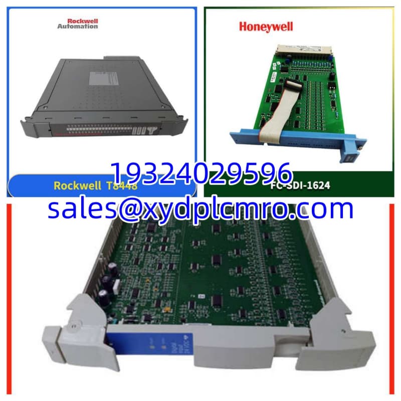
- Mounting: Tricon I/O chassis slot; hot-swappable
- Form Factor: Standard Tricon I/O module width; exact H × W × D varies by chassis generation — verify with the OEM mechanical drawing for the installed Tricon rack
- Weight: Approximately 0.5–1.0 kg per module (estimate; confirm with OEM datasheet)
- Terminal Notes: 4 analog output channels; external 24 VDC loop power required; 0 VDC and 36 VDC continuous overvoltage protection per channel
- Wiring: Use shielded twisted-pair cable for 4–20 mA loops; terminate shield at one end only
- Loop Load Check: Before commissioning, calculate V_required = 0.02 A × R_loop + headroom. If the loop supply is 24 VDC, keep total loop resistance below approximately 700 Ω for reliable 20 mA output.
FAQ
Is the TRICONEX 3481 an analog output or a communication module?
The 3481 designation appears in both contexts across third-party sources. The AO 3481 variant is a 4-channel 4–20 mA analog output module for the Tricon system. Always verify the front label, function code, and TriStation configuration before treating it as a direct replacement.Can I replace a failed 3481 without shutting down the Tricon system?
Yes. Tricon I/O modules are hot-swappable. However, confirm that the affected output loops are in a safe state before removal, especially if the module drives ESD valves or trip actuators.What happens if one channel fails?
The TMR architecture and FSD diagnostics isolate the fault to the affected channel. The remaining channels continue to operate, and the module generates a diagnostic alarm.Do I need external loop power?
Yes. The 3481 analog output module requires external 24 VDC loop power. It does not source loop power internally in the same way a two-wire transmitter supply would.Can I use it with a DCS that expects 0–10 V?
No. The 3481 is a 4–20 mA current output module. If your downstream device expects 0–10 V, you need a current-to-voltage converter or a different I/O module.What firmware or software do I need to configure it?
TriStation 1131 or the site-approved Tricon configuration tool. Record the existing channel configuration before replacing the module, and verify firmware compatibility with the Tricon processor.I received a 3481 but it doesn’t match my old card. What should I check?
Compare the full part number, front label, connector type, channel count, and function code. Some “3481” listings refer to communication or other I/O modules, not the AO 3481 analog output. If the label or connector differs, do not install it until verified.