

 Tel:
 Email:
 WhatsApp:
Description
Key Technical Specifications
| Parameter | Detail |
|---|---|
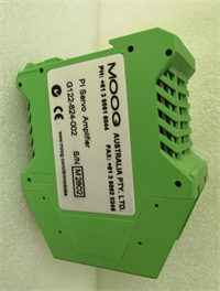
| Part Number | G122-824-002 |
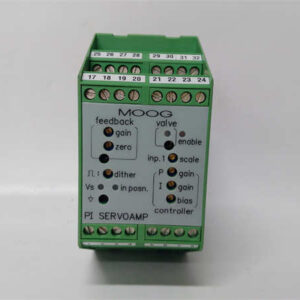
| Product Type | P-I Servo Amplifier |
| Control Mode | Proportional (P), Integral (I), or P-I |
| Supply Voltage | 24 VDC nominal, 22–28 VDC |
| Supply Current | Approx. 75 mA no-load; approx. 200 mA at 100 mA load |
| Input Signals | 3 inputs: 2 single-ended, 1 differential |
| Input 1 | Single-ended, selectable 4-20 mA or ±10 V |
| Input 2 | Single-ended, selectable 4-20 mA or ±10 V (-002 adds 4-20 mA option) |
| Feedback Input | 4-20 mA or ±10 V selectable |
| Sensor Excitation | +10 V at 10 mA |
| Output | Current or voltage output to drive Moog servovalves |
| Proportional Gain | 1 to 20 |
| Integrator Gain | 1 to 45 per second |
| Error Amplifier Bias | ±1.5 V |
| Special Features | Output step push button, dither, enable input, “in-position” output |
| Mounting | DIN-rail module |
| Certification | CE marked |
| Reference | Moog G122-824 P-I Servo Amplifier documentation |
Product Introduction
If you have ever chased a hydraulic actuator that would not hold position, you already know why the G122-824-002 still shows up in field cabinets. It is not a fancy digital drive. It is an analog P-I servo amplifier that sits between your controller and a Moog servovalve, sums command and feedback, and produces a clean current or voltage output. That simplicity is why it survives on test rigs, turbine controls, rolling mills, and older flight-control test benches.The -002 revision matters. Compared with the G122-824-001, it adds a 4-20 mA option on Input 2, an output step push button for loop tuning, and improved thermal performance. That makes it easier to match process instrumentation loops without adding external converters. The front-panel trim pots, LEDs, and test points are old-school, but they save hours when you are commissioning a loop at 2 a.m. I would not call it plug-and-play. It is plug-and-verify. Get the switches wrong and the valve will hunt, drift, or refuse to enable.
Quality SOP & Tech Pitfalls
The Lab Report (SOP)
- Visual and counterfeit check: verify Moog labeling, revision “-002,” housing condition, terminal integrity, and signs of prior repair.
- Power-up test: apply 24 VDC within 22–28 VDC range; check LED status and absence of abnormal heating.
- Input verification: confirm Input 1, Input 2, and feedback input respond correctly to 4-20 mA or ±10 V as configured.
- Output check: measure output signal behavior and confirm it follows command changes without saturation or oscillation under no-load test conditions.
- Configuration logging: record switch positions, trim-pot settings, jumper state, and serial number before packing.
- Final packing: anti-static bag, foam protection, and sealed carton with test record.
A Fluke 115 or equivalent multimeter is enough for basic checks. For full loop validation, use the actual servovalve or a calibrated load box.The Engineer’s Warning (Pitfalls)Do not assume “-002” means “same settings as -001.” The -002 added Input 2 4-20 mA capability and the output step button. If you swap them without photographing the old module, you will spend half a day wondering why the loop is unstable. I have seen a turbine test stand oscillate for hours because someone left the integrator enabled while the feedback range was set wrong.ESD kills these cards quietly. A module can power up, show normal LEDs, and still drift under thermal load. Handle it like an LVDT cable: grounded, shielded, and respected. Also, never ignore the “enable” input. If the valve moves when you apply power, your safety logic is incomplete.
Installation & Configuration Guide
1. Pre-Installation⚠️ Shut down the hydraulic power unit and isolate pressure before touching wiring.
⚠️ Discharge stored energy in accumulators.
⚠️ Photograph every switch, jumper, trim-pot position, and terminal label on the old G122-824 module.
Verify the supply is 24 VDC and within 22–28 VDC.2. RemovalLabel each wire before disconnecting. Note Input 1, Input 2, feedback, output, enable, and sensor excitation connections. Release the DIN-rail clip carefully. Do not pry the housing.3. InstallationCopy all DIP switch and jumper settings from the old module. This prevents most startup failures. Seat the G122-824-002 firmly on the DIN rail. Reconnect wiring exactly as labeled. Keep analog signal cables away from valve power leads and VFD outputs.4. Power-On & TestingApply 24 VDC with the valve disabled. Verify LED indicators. Check sensor excitation voltage. Enable the output at low command. Use the output step button to confirm direction and gain response. Tune proportional gain, integrator gain, and dither only after confirming feedback polarity. If the actuator moves in the wrong direction, reverse feedback or command polarity before increasing gain.
Compatible Replacement Models
| Compatibility Tier | Model | Notes |
|---|---|---|
| ✅ Drop-in Replacement | G122-824-002 | Same Moog P-I amplifier family; confirm switch settings, input ranges, and output configuration before installation |
| ⚠️ Functional Predecessor | G122-824-001 | Older revision; lacks Input 2 4-20 mA option and output step button; may still work if configured correctly |
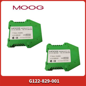
| ⚠️ Series Alternative | G122-829-001 | Similar DIN-rail servo amplifier family; not a guaranteed drop-in; verify I/O, gain structure, and valve compatibility |
| ❌ Not Directly Compatible | Moog G123, D660-series valve electronics, modern digital drives | Different platforms; requires re-engineering, rewiring, or full control migration |
Frequently Asked Questions (FAQ)
Can I replace a G122-824-001 with a G122-824-002?
Yes, in most cases. The -002 is the functional successor. It adds 4-20 mA on Input 2, an output step button, and better thermal behavior. You still must copy the original switch and trim-pot settings.Is this a digital controller?
No. It is an analog P-I servo amplifier. There is no Ethernet, Profibus, or fieldbus interface. That is actually why many plants keep it: fewer firmware dependencies and fewer communication timeouts.What valves can it drive?
It is designed for Moog servovalves and proportional valves that accept analog current or voltage drive. The exact output range must be confirmed from the Moog datasheet and the valve nameplate. Do not guess the current limit.Can I hot-swap it?
Not recommended. Remove power, isolate the valve, and verify enable logic before swapping. Hydraulic systems do not forgive surprise movements.What causes oscillation after replacement?
Usually wrong feedback polarity, integrator enabled too early, excessive proportional gain, or mismatched input range. Start with low gain, confirm feedback direction, then increase integrator action.Do you provide calibration certificates?
Only if explicitly requested and supported by the test setup. Standard supply includes power-up, input/output, and configuration verification. Full bench calibration requires the actual valve or a certified load simulator.Is the G122-824-002 still produced by Moog?
Availability should be confirmed directly with Moog or an authorized distributor. In the aftermarket, units are commonly supplied as new surplus or tested used stock. Always verify the revision label before purchase.