 Tel:
Tel:  Email:
  WhatsApp:
 Description
Key Technical Specifications
| Parameter | Value |
|---|---|
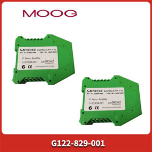
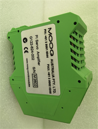
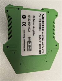
| Manufacturer | MOOG |
| Model Number | G122-824-002 |
| Product Type | P-I Servo Amplifier |
| Control Modes | Proportional (P), Integral (I), Proportional-Integral (PI) |
| Input Channels | 2 x Single-Ended, 1 x Differential |
| Input Signal | ±10V or 4-20mA (configurable) |
| Output Signal | ±10V or ±5/10/20/30/50/100mA (configurable) |
| Power Supply | +24V nominal (22-28V range) |
| Operating Temp | 0 to +40°C |
| Mounting | DIN Rail (100W x 108H x 45D mm) |
| Certification | CE Marked |
Product Introduction
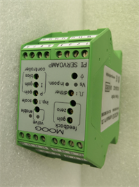
The MOOG G122-824-002 is a high-performance, user-configurable P-I (Proportional-Integral) servo amplifier designed for precise closed-loop control of hydraulic or pneumatic actuators. As part of MOOG’s G122 series, this DIN rail-mounted module is engineered to accept a variety of input signals and convert them into amplified outputs to drive servo and proportional valves.This device stands out for its flexibility, allowing users to select between P, I, or PI control modes via internal switches to optimize system response. It features two single-ended input channels and one differential feedback input, supporting both ±10V and 4-20mA signal types. The unit is capable of driving a wide range of industrial valves and is commonly used in applications requiring high-precision motion, force, or position control.
Installation & Configuration Guide
Preparation
- Verify the unit is the correct model (G122-824-002) and matches your system’s electrical requirements.
- Ensure the DIN rail in your control panel is clean and free of debris.
- Safety: Disconnect all power to the control panel before beginning any installation or wiring.
Removal
- If replacing an existing unit, carefully disconnect all wiring harnesses.
- Note the position of any DIP switches or jumpers for reconfiguration later.
- Slide the unit out of the DIN rail slot.
Installation
- Align the G122-824-002 with the DIN rail.
- Press firmly until the unit clicks into place on the rail.
- Reconnect all wiring to the corresponding terminals, ensuring all connections are tight.
Power-On & Test
- Restore power to the control panel.
- Check the front panel LEDs: “Vs” (supply) should be green, “Enable” yellow, and “Position” green if active.
- Apply a test input signal and verify the output drives the connected valve correctly.
- Use the front panel “Output Step” button to verify loop stability.
Troubleshooting Quick Reference
| Symptom | Probable Cause | Action |
|---|---|---|
| No Power | Loose connection or blown fuse | Check 24VDC supply and fuse; inspect terminal block. |
| Output Not Responding | Incorrect control mode setting | Verify internal DIP switch settings for P/I/PI selection. |
| Erratic Movement | Feedback signal noise | Check feedback sensor wiring; ensure shielded cable is grounded. |
| Overheating | Exceeding thermal limits | Verify ambient temperature is within 0-40°C range; ensure proper airflow. |
Dimensions, Mounting & Wiring Notes
- Dimensions: 100 mm (W) x 108 mm (H) x 45 mm (D)
- Mounting: DIN rail (EN 60715) – standard 35mm rail.
- Wiring: Input and output terminals are screw-type. The unit supports both ±10V and 4-20mA signal types via internal jumpers.

G122-824-002 MOOG
FAQ
What is the difference between G122-824-002 and 001?
The -002 is an updated version of the -001. It features improved thermal performance, an added 4-20mA option on Input 2, and a dedicated “Output Step” button for easier loop tuning.
MOOG G122-824-002 servo amplifier
What types of valves can this drive?
This amplifier is designed to drive MOOG servo valves and proportional valves, particularly those requiring a high-impedance current or voltage drive signal.
Can I use this for position control?
Yes. The unit includes a differential feedback input for position sensors and supports PI control, making it suitable for precise position control loops.
What is the purpose of the “Dither” function?
The 200Hz dither signal is an AC bias applied to the valve coil to reduce stiction and friction, ensuring smoother low-speed motion and better control resolution.
Does this unit require special software?
No, configuration is handled via front panel switches and jumpers. However, advanced tuning may require an oscilloscope or multimeter.