


 Tel:
 Email:
 WhatsApp:
Description
Key Technical Specifications
| Parameter | Specification |
|---|---|
| Base Model | IS200TBAIH1C (suffix CCC denotes PCB revision/batch) |
| Board Type | Analog I/O Terminal Board (no A/D or D/A conversion onboard) |
| Analog Inputs | Multiple AI channels |
| Analog Outputs | Multiple AO channels |
| AI Signal Types | 4-20 mA, ±5 V DC, ±10 V DC |
| AO Output Range | Jumper-selectable, typically mA-range outputs |
| Field Connectors | TB1, TB2 (removable terminal blocks) |
| Processor Connectors | JS1, JT1, JR1 (37-pin, fan-out to VAIC boards) |
| Redundancy Support | Simplex and TMR (Triple Modular Redundant) |
| System Compatibility | GE Speedtronic Mark VI; not directly compatible with Mark VIeS |
| Protection | MOV surge suppression, high-frequency noise filtering |
| Diagnostics | Channel open/short diagnostics handled by paired VAIC processor board |
Product Introduction
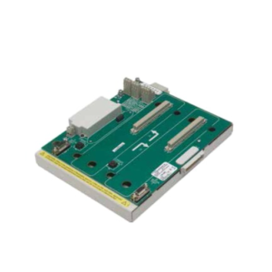
Let me be blunt: this board does not “process” anything. It sits there, takes your field wiring, and passes it along. That is exactly what it is supposed to do. The IS200TBAIH1CCC is a GE Speedtronic Mark VI analog I/O terminal board, and its only job is to terminate field signals—pressure transmitters, flow meters, valve positioners—and route them to the VAIC analog processor board for actual conversion and voting logic.Engineers keep these in stock because when one fails, the turbine does not wait for a datasheet. The multiple analog input and output channels cover most critical process loops. The three 37-pin connectors (JS1, JT1, JR1) are what make TMR possible: the same signal goes to separate VAIC boards for majority voting. That is the whole point of this architecture. One thing I will flag: different PCB revisions of the TBAIH1C family have different jumper maps. The CCC suffix matters. Do not assume a board pulled from a different rack is a drop-in match.

Quality SOP & Tech Pitfalls
The Lab Report (SOP):
- Visual/Counterfeit Check: Inspect PCB silk screen, solder joints, connector pin alignment, and GE part markings.
- Continuity & Insulation: Multimeter check on TB1/TB2 terminals and JS1/JT1/JR1 pinouts against the OEM wiring diagram. Insulation resistance check between signal groups.
- Jumper Verification: Photograph and log every jumper position. This is where most replacements fail.
- Live Test on Test Rack: Inject standard analog signals into AI channels; verify pass-through to the 37-pin connectors. Test AO output with a loop calibrator.
- Firmware/Revision Logging: Record the PCB revision label. The paired VAIC board firmware must match the terminal board revision.
- Anti-static Sealing: Bag with ESD protection, include test report and jumper photo.
The Engineer’s Warning (Pitfalls):
- Jumper mismatch is the number-one cause of “bad readings” after a swap. I once watched a crew replace a TBAIH1C, skip the jumper check, and spend hours chasing a phantom 4-20 mA drift on a fuel flow transmitter. The new board had different default jumpers. The signal was fine; the board was scaled wrong.
- Do not hot-swap the 37-pin connectors while the VAIC boards are powered. You will get arcing on the backplane pins. I have seen corroded JS1 pins cause intermittent channel faults that took weeks to diagnose.
- Revision mismatch. A TBAIH1C rev from an early Mark VI rack may not map channels the same way as a CCC revision. Always cross-reference with the OEM hardware manual before commissioning.
Installation & Configuration Guide
Phase 1 — Pre-Installation ️
- Follow plant LOTO procedures. Confirm the turbine is in a safe shutdown state.
- Wait for capacitor discharge. Verify with a multimeter.
- Photograph every jumper, every terminal wire, and all three 37-pin cable labels. This step prevents the majority of commissioning failures.
Phase 2 — Removal
- Label each wire at TB1 and TB2 before disconnecting.
- Disconnect JS1, JT1, JR1 cables carefully—do not pull on the wires; pull on the connector shells.
- Release the DIN/card retention clips and slide the board out.
Phase 3 — Installation
- Copy all jumper settings from the old board to the new board before installing. Verify each one twice.
- Seat the new board firmly. Reconnect JS1, JT1, JR1 in the correct order (verify cable labels against your photos).
- Reconnect TB1/TB2 field wiring per your labels.
Phase 4 — Power-On & Testing
- Verify DC supply to the I/O rack before energizing.
- Power up and observe LED boot sequence on the paired VAIC board(s).
- Inject known signals into each AI channel and verify readings on the HMI.
- Test both AO channels with a loop calibrator.
- Confirm no channel fault alarms are active before returning the turbine to service.

Compatible Replacement Models
| Tier | Model | Notes |
|---|---|---|
| Drop-in Replacement | IS200TBAIH1CCC | Same base model (IS200TBAIH1C). Verify PCB revision and jumper map match the original. |
| ️ Software Compatible | IS200TBAIH1C (other suffixes) | Same base board, but jumper settings and channel mapping may differ by revision. Requires jumper reconfiguration and full channel verification. |
| Hardware Mod Required | IS200TBAIH1B or earlier revisions | Different jumper/channel definitions. Not recommended as a direct swap unless the entire I/O rack is being reconfigured. |
| Not Compatible | Mark VIeS or Mark V TCQA-based boards | Different architecture and connectors. Requires full system migration. |
Frequently Asked Questions (FAQ)
Can I hot-swap this board while the turbine is running?
No. The IS200TBAIH1CCC is a terminal board connected to live VAIC processor boards. Pulling the 37-pin connectors under load risks backplane damage and will likely trip the affected I/O channels. Plan a controlled outage.Does this board do A/D conversion?
No. It has zero processing capability. All analog-to-digital conversion happens on the paired VAIC board. If your AI channels are reading garbage, the fault could be on the VAIC side, not this terminal board.Is IS200TBAIH1CCC the same as IS200TBAIH1C?
Yes. IS200TBAIH1C is the base model; CCC is the revision/suffix code. However, different suffixes can have different jumper defaults and PCB layouts. Always compare jumper positions before installing.Can I use this on a Mark VIeS system?
No. Mark VIeS uses a different I/O architecture. This board is specific to the legacy Mark VI platform.What happens if the jumpers are wrong?
You will get scaled readings, reversed polarity, or open-circuit faults on affected channels. In a TMR setup, one bad channel can cause a mismatch vote and trigger a nuisance alarm—or worse, a false trip.How do I verify the board is genuine?
Check the GE silk screen, PCB revision label, connector quality, and part number stamping. Counterfeit industrial boards often have misaligned holes, poor solder joints, or missing revision markings. Request a test report from the supplier.Does it come with a warranty?
That depends on the supplier. Reputable surplus distributors typically offer a warranty on new original stock. Verify this in writing before purchasing.