 Tel:
Tel:  Email:
  WhatsApp:
 Description
Key Technical Specifications
| Parameter | Specification | Notes |
|---|---|---|
| Communication | EtherCAT Real-Time Ethernet | High-speed fieldbus |
| Sync Time | ≤ 1 ms (100 axes) | Distributed clock precision |
| Jitter | ± 20 ns | Critical for coordinated motion |
| Bandwidth | 2 kHz | Velocity loop response |
| Encoder Support | Up to 18-bit (4.94 arc-seconds) | High-resolution feedback |
| Operating Temp | 0°C to +40°C | Derate above 40°C |
| Storage Temp | -20°C to +60°C | Non-freezing |
| Humidity | 20% – 80% RH | Non-condensing |
| Protection | IP67 (System dependent) | Check connector seals |
| Mounting | Flange / DIN Rail | Depends on host chassis |
| Vibration | 49 m/s² | IEC standard compliant |
Product Introduction
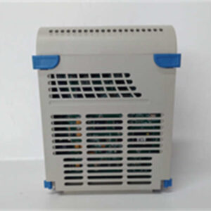
In high-speed packaging or printing lines, “close enough” gets you a pile of scrap material and a furious plant manager. The EMERSON 5X00605G01 isn’t just another IO card; it’s the brain that keeps a hundred moving parts dancing in perfect rhythm. I’ve seen generic controllers try to handle complex cam profiles and fail because they couldn’t keep up with the bus cycle time. This module, however, is built for the heavy lifting of synchronized motion.What makes this unit stand out is the 2kHz velocity loop bandwidth combined with that incredibly tight ±20ns synchronization jitter. Most standard PLCs struggle to update outputs fast enough to prevent “jerk” during rapid direction changes. This module handles the EtherCAT traffic with such low latency that you can synchronize 100 axes in under a millisecond. It’s designed to sit inside a drive system (often paired with SV630 series hardware) and offload the timing-critical logic from the main CPU. If you are running a machine where one axis lagging by a fraction of a second ruins the whole batch, this is the hardware you need to trust.
Quality SOP & Tech Pitfalls (The Reality Check)
The Lab Report (SOP)
We don’t just look at the box. Here is how we verify these units before they leave our bench:
- Visual Inspection: We check the PCB for cold solder joints or capacitor swelling. Since this is often a replacement part, we inspect the gold-finger connectors for wear—scratches here cause intermittent data loss.
- Live Bus Test: We mount the module in a test rack and fire up an EtherCAT master. We monitor the “Link” and “Run” LEDs to ensure it establishes a handshake within milliseconds.
- Signal Integrity: Using an oscilloscope, we verify the differential signal quality on the bus ports to ensure no noise is bleeding into the comms line.
- Firmware Check: We read the onboard chip version. Mismatched firmware is the #1 reason for returns, so we log exactly what revision is installed.
- ESD Packing: Finally, it goes into a static-shield bag with desiccant. Humidity kills these boards during shipping.
The Engineer’s Warning (Pitfalls)
Don’t ignore the grounding.
I once spent three days chasing a “ghost fault” on a machine that would randomly fault out on “Sync Error.” Turned out the shield on the EtherCAT cable wasn’t grounded at the drive end. The 5X00605G01 is sensitive to electromagnetic interference (EMI). If you run this next to a high-voltage contactor without proper shielding, you will get communication dropouts. Also, check your DIP switches—there are usually tiny switches on the board for termination resistance. If you forget to toggle these on the last node of the chain, the whole network crashes.
Installation & Configuration Guide
Swapping this module requires attention to detail. It’s not just plug-and-play if the configuration doesn’t match.
- Pre-Installation (Safety First)
- Lockout/Tagout: Cut the main power. Wait 5 minutes for the DC bus capacitors to discharge.
- Documentation: Take a clear photo of the old module’s DIP switch settings and rotary dials. Do not rely on memory.
- Cabling: Label your EtherCAT IN and OUT cables. They look identical but function differently.
- Removal
- Disconnect the fiber/copper EtherCAT cables carefully. Do not yank by the wire; pull by the connector head.
- Release the locking clips or screws securing the module to the backplane or rail.
- Installation
- Insert the 5X00605G01 firmly into the slot. You should hear a solid click or feel it seat fully against the backplane.
- CRITICAL STEP: Set the DIP switches and rotary address dials to match the old unit exactly. If the address is wrong, the master controller won’t see it.
- Reconnect the EtherCAT cables. Ensure the “OUT” port of the previous module goes to the “IN” port of this one.
- Power-On & Testing
- Restore power. Watch the LED sequence. typically, “PWR” lights green, then “RUN” flashes.
- If “ERR” lights up red, check your node address settings immediately.
- Connect your laptop via the service port (if available) or HMI to verify the drive recognizes the module version.
Compatible Replacement Models
If you cannot source the exact 5X00605G01, you may have to look at the system level. This module is often part of a larger drive ecosystem.
| Compatibility | Model Number | Notes |
|---|---|---|
| ✅ Direct Match | 5X00605G01 | Exact replacement. Verify firmware version matches existing system. |
| ⚠️ System Upgrade | SV630 Series Drive | This module is often integrated into or compatible with the SV630 architecture. You might need to replace the whole drive unit. |
| ❌ Not Compatible | Standard VFDs | Do not try to substitute this with a generic Variable Frequency Drive. This is a servo motion controller, not a simple motor speed controller. |

Frequently Asked Questions (FAQ)
Q: Can I hot-swap this module while the machine is running?
A: Absolutely not. While some modern PLCs support it, this is a motion control interface dealing with active servo loops. Pulling it live will cause an immediate following error and likely crash the machine or damage the motor drives. Power down first.Q: My “EtherCAT” light is blinking orange. What does that mean?
A: That usually indicates a topology error or a baud rate mismatch. Check that your cables are plugged into the correct IN/OUT ports and that the termination switch (if present on the last node) is engaged.Q: Does this support absolute encoders?
A: Yes. The specs indicate support for high-resolution feedback (up to 18-bit), which is standard for absolute positioning. However, you need to configure the drive parameters to recognize the specific encoder protocol (e.g., Tamagawa, Nikon).Q: Is this module compatible with Rockwell or Siemens PLCs?
A: Indirectly, yes. Since it uses EtherCAT, it can communicate with any master (Siemens, Beckhoff, etc.) that has an EtherCAT master card. However, you will need the ESI (EtherCAT XML) file from Emerson to import into your PLC engineering software.Q: The unit looks physically different from my old one, but the model number is the same. Is it fake?
A: Emerson, like many manufacturers, updates revisions. As long as the connector layout and the electrical specs (voltage/current) match, a physical revision change (Rev A vs Rev B) is usually safe. Just be careful with mounting screw locations.