 Tel:
Tel:  Email:
  WhatsApp:
 Description
Key Technical Specifications
| Parameter | Specification | Notes |
|---|---|---|
| Output Current | 200 A (Max Continuous) | High-current capability |
| Output Voltage | 100 V DC | Regulated output |
| Power Rating | 20 kW | Suitable for industrial lasers |
| Efficiency | > 90% | Reduces heat generation |
| Control Mode | Constant Current / Constant Power | User selectable |
| Protection | Over-current, Over-voltage, Over-temp | Active shutdown |
| Operating Temp | -20°C to +60°C | Wide industrial range |
| Ingress Protection | IP65 | Dust-tight and water-resistant |
| Interface | Analog/Digital Control Inputs | Multi-mode control |
| Application | Laser Diode Driving | High precision required |
Product Introduction
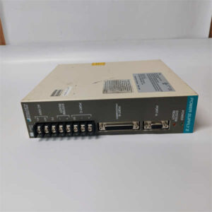
When you are pushing 20 kilowatts of power through a circuit, “good enough” efficiency isn’t just a buzzword—it’s the difference between a cool-running machine and one that melts itself. The RELIANCE SR3000 2SR40700 is a beast designed for exactly this kind of heavy lifting. I’ve seen these modules sitting in laser welding cells where the ambient temperature hits 50°C, and they just keep humming along. It’s not a delicate logic board; it’s a power plant component.What sets this specific unit apart is its ability to handle 200A with >90% efficiency. In the world of laser diode driving, ripple and stability are everything. If the current fluctuates, your laser intensity wavers, and your weld quality tanks. This module uses high-grade power conversion tech to ensure that whether you are marking a microchip or cutting thick plate steel, the power delivery is dead flat. It’s built like a tank (IP65 rated), meaning it doesn’t need a climate-controlled cabinet, which is a massive plus for retrofits in dirty environments.
Quality SOP & Tech Pitfalls (The Reality Check)
The Lab Report (SOP)
We treat high-power modules like this with extreme caution. Here is our verification process:
- Visual Inspection: We inspect the heavy-gauge busbars and connectors for any signs of arcing or thermal stress (discoloration). We also check the potting compound for cracks, which can lead to moisture ingress.
- High-Pot Test: We perform an insulation resistance test (Megger) on the input/output terminals against the chassis ground to ensure the isolation barrier is intact.
- Load Bank Test: We hook it up to a resistive load bank and ramp it up to 50% capacity. We monitor the output waveform on an oscilloscope to check for noise or instability in the constant current loop.
- Thermal Imaging: While under load, we scan the heatsinks with a thermal camera to ensure even heat distribution. Hot spots indicate bad thermal paste or loose internal connections.
- Final Packing: It is packed in anti-static foam within a double-walled box to prevent physical shock during transit.
The Engineer’s Warning (Pitfalls)
Watch your grounding and cooling.
I saw a project delayed by two weeks because a technician installed one of these without proper thermal paste on the mounting surface. The module has over-temp protection, so it would run for ten minutes, hit 85°C, and shut down. It looked like a “bad unit,” but it was just starving for heat transfer. Also, at 200A, even a milliohm of resistance in a loose connection creates massive heat. Torque your terminals to spec. Finally, verify your control signal—feeding a 10V command into a 5V input will fry the logic interface instantly.
Installation & Configuration Guide
This isn’t a DIN-rail clip-on; this is heavy infrastructure. Treat it accordingly.
- Pre-Installation
- Safety: Verify main disconnect is OPEN and locked out. Capacitors can hold charge.
- Mounting: Ensure the mounting surface is flat, clean, and conductive (if using chassis cooling). Apply thermal compound if specified in the manual.
- Check Ratings: Confirm your incoming AC supply matches the rectifier requirements (if applicable) and that your cabling is sized for 200A.
- Wiring
- Power Cables: Use crimped lugs, not bare wire. Connect the heavy gauge output cables to the load (laser head/motor).
- Shielding: Shield your control cables (analog inputs). At 20kW, the electromagnetic interference (EMI) generated can induce false signals in unshielded wires. Ground the shield at one end only to avoid ground loops.
- Configuration
- Mode Selection: Set the jumpers or software parameters for Constant Current (CC) or Constant Power (CP) mode depending on your application. Lasers usually require CC.
- Limits: Set the maximum current limit pot/software value slightly below the laser diode’s damage threshold.
- Power-Up
- Enable the control voltage first. Check for “Ready” status.
- Slowly ramp up the reference signal while monitoring the output amperage with a clamp meter. Do not jump straight to 100%.
Compatible Replacement Models
Finding a direct drop-in for legacy Reliance power modules can be tough. You often have to look at system replacements.表格
| Compatibility | Model Number | Notes |
|---|---|---|
| ✅ Direct Match | SR3000 2SR40700 | Exact replacement. Essential for maintaining original system architecture. |
| ⚠️ System Retrofit | Custom Laser Driver | Companies like LDP or Starlabo make universal high-power drivers. Requires re-wiring and potentially new control logic. |
| ❌ Not Compatible | Standard Servo Drives | Do not use standard motion control servos (like Kollmorgen or Baldor standard drives) unless they are specifically rated for resistive/laser loads. The control loop dynamics are different. |
Frequently Asked Questions (FAQ)
Q: Can I use this to drive a standard DC motor?
A: Technically yes, it provides DC current. However, it is optimized for the inductive load characteristics of a laser diode. If you use it for a motor, ensure the back-EMF doesn’t exceed the 100V rating, or you will blow the output transistors.Q: The module trips immediately on start-up. What gives?
A: Check for a short circuit in your load (the laser head or cabling). With 200A available, even a tiny short will trigger the over-current protection instantly. Also, verify the “Enable” signal wiring; a floating enable line can sometimes cause erratic behavior.Q: Is the IP65 rating valid for the whole unit?
A: The enclosure is IP65, but once you punch holes in it for conduit fittings or cables, that rating is compromised unless you use proper cable glands and seals. Don’t expect it to survive being hosed down if the cable entry isn’t sealed perfectly.Q: Does this support remote monitoring?
A: Yes, the specs mention multiple control interfaces. It typically supports analog inputs (0-10V / 4-20mA) for setpoints and often has digital handshake lines. Check the specific pinout on the terminal block for “Monitor” outputs to feed data back to your PLC.Q: How do I know if the efficiency is actually 90%?
A: You can calculate it by measuring Input Power (Watts) vs. Output Power (Volts x Amps). If the difference is huge and the heatsink is scorching hot, the internal components might be degraded. A healthy unit should run relatively cool at partial loads.