 Tel:
Tel:  Email:
  WhatsApp:
 Description
Key Technical Specifications
| Parameter | Specification | Notes |
|---|---|---|
| Input Type | Voltage / Current / RTD / TC | Configurable via software/jumpers |
| Channels | 8 Differential Inputs | Field-side isolated |
| Resolution | 16-bit ADC | High precision for noisy environments |
| HART Protocol | Integrated Bell 202 Modem | Supports AMS Device Manager |
| Input Impedance | >10 MΩ (Voltage) / 50 Ω (Current) | Standard loading |
| Update Rate | 50ms typical (all 8 channels) | Scan time varies by controller load |
| Isolation | 500V AC (Channel to Logic) | Prevents ground loops |
| Operating Temp | -20°C to +60°C | Derate above 50°C |
| Power Dissipation | ~4.5 Watts | Generates heat; ensure rack airflow |
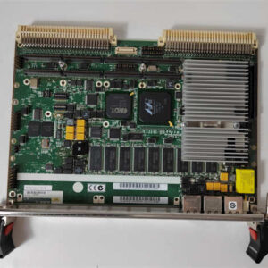
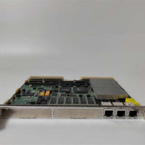
| Dimensions | 5.0″ x 7.5″ (Standard Ovation Card) | Eurocard form factor |
Field Engineer’s Perspective
Let’s be honest: the Ovation system is the backbone of countless power plants and water treatment facilities, mostly because it doesn’t quit easily. The 5X00106G02 isn’t just a generic AI card; it’s the interface for your critical loop tuning. I’ve deployed these in boiler feedwater applications where signal noise was a nightmare. Because this module offers field-side isolation, it kills ground loops dead. If you’re seeing fluctuating values on a level transmitter that should be steady, swapping in one of these usually fixes the electrical gremlins.The real value here is the “Fast HART” capability. In the old days, you had to carry a handheld communicator to the junction box to change damping or range on a smart transmitter. With this card installed, you can do it from the control room using AMS. It saves hours of walking the catwalks. Just make sure your Ovation controller firmware is recent enough to talk to it—I once spent three hours troubleshooting a “bad card” only to realize the controller didn’t have the device description (DD) files loaded.
Quality SOP & Tech Pitfalls
The Lab Report (SOP)
Before we ship a 5X00106G02, we don’t just wipe it off and box it.
- Visual Inspection: We check the PCB for “fried” traces near the terminal blocks—common if someone torqued the wires too hard. We also look for bulging capacitors, a sign of age.
- Live Loop Test: We hook it up to a Fluke calibrator and simulate a 4-20mA signal. We verify the digital readout matches the input within the ±0.1% tolerance.
- HART Handshake: We connect a HART modem to the test rack to ensure the module can actually “talk” to a transmitter. If the handshake fails, the card goes to repair.
- Burn-In: We run it at 50°C for 4 hours. If it drifts, it doesn’t ship.
The Engineer’s Warning (Pitfalls)
Here is where guys get burned: Addressing and Jumpers.
This card often has hardware address jumpers or switches depending on the revision. If you pull a card and don’t document the jumper positions before pulling a “new” one, you might plug in the replacement and find the controller can’t see it because the slot ID is wrong.
Field Horror Story: A tech at a combined cycle plant swapped a bad card with a spare but forgot to move a single shunt jumper. He spent six hours rebooting the controller, thinking it was a comms failure. It was just a missing jumper. Always photograph the old card first.
Installation & Configuration Guide
- Pre-Installation Safety
- ⚠️ CRITICAL: Ensure the rack power is OFF or the specific slot is de-energized if hot-swap is not supported by your specific chassis revision. Static discharge will kill these inputs instantly. Touch the rack frame before handling the PCB.
- Removal & Documentation
- Unscrew the faceplate retaining screws.
- Take a photo of the front DIP switches and internal jumpers.
- Gently rock the card side-to-side to disengage it from the backplane connector. Do not pry against the PCB components.
- Hardware Setup
- Compare the new 5X00106G02 with your photo. Move any jumpers to match the original configuration exactly.
- Insert the card into the slot. Apply even pressure to the top and bottom edges until the backplane connector seats fully.
- Wiring & Power-Up
- Re-attach the field wiring terminals. Torque to spec (usually finger-tight plus a quarter turn).
- Power up the rack. Watch the LED status lights.
- Green = OK. Flashing Red usually means a configuration mismatch or a bad EEPROM.
- Verification
- Go to the operator interface. Force a known mA value and verify the process variable reads correctly.
Compatible Replacement Models
| Compatibility Tier | Model Number | Notes |
|---|---|---|
| ✅ Drop-in Replacement | 5X00106G02 | Exact match. Ensure suffix/revision is compatible with your Ovation version (e.g., v3.x vs v4.x). |
| ⚠️ Functional Equivalent | 5X00106G01 | Earlier revision. May require a firmware update on the controller to recognize the newer G02 features. |
| ❌ Not Compatible | 5X00105G01 | This is an Analog Output (AO) module. Physically similar, but plugging it in will cause a fault. |
Frequently Asked Questions (FAQ)
Q: Can I hot-swap this while the turbine is running?
Technically, Ovation supports hot-swapping, but I wouldn’t risk it on a critical protection loop unless I had redundant controllers active and synced. Pulling a card creates a momentary open circuit; if the logic isn’t programmed to handle “Bad PV,” it could trip the unit.Q: The “Module Fault” LED is flashing red. What gives?
Usually, this means the card isn’t configured in the database, or the checksum is bad. Check your controller’s event log. If it says “Invalid Configuration,” you need to download the point definitions from the engineering workstation.Q: Does this support RTDs (Temperature sensors)?
Yes, but you have to select the correct input type in the software configuration. You might also need to install specific termination resistors or use a dedicated RTD terminal board depending on your cabinet layout.Q: Why is my HART communication timing out?
Check the load resistance. HART needs at least 250 ohms to communicate. If your loop impedance is too low, the modem inside the 5X00106G02 won’t detect the signal. Also, ensure no other HART masters (like handhelds) are connected simultaneously.Q: How long is the warranty on these?
Standard industry practice is 12 months. Since these are complex electronic assemblies, avoid buying “untested” surplus. You want a supplier who guarantees the firmware is intact.