 Tel:
Tel:  Email:
  WhatsApp:
 Description
Key Technical Specifications
- Module Type: Digital Output (SDV541 series)
- Number of Channels: 16 isolated channels
- Output Voltage: 24V DC
- Isolation: Module-level isolation
- Terminal Type: Pressure clamp terminal or MIL cable (Non-explosion proof)
- Operating Temperature: 20 to 70°C (ISA Standard G3)
- Mounting Style: Standard density installation
- System Compatibility: CENTUM CS3000, ProSafe-RS
- Suffix Code Breakdown: -S (Standard), 5 (Non-Ex terminal), 3 (Standard Temp)
- Optional Accessories: Error insertion prevention pin (/PRP), MIL cable connector covers
Product Introduction
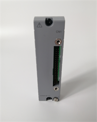
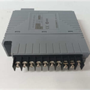
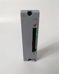
The YOKOGAWA SDV541-S53 is a 16-channel digital output module designed for the CENTUM CS3000 and ProSafe-RS distributed control systems (DCS). It serves as a critical interface in the Field Control Station (FCS), converting digital control logic into physical 24V DC signals to drive field devices like relays, solenoid valves, and indicator lights.This module features module-level isolation, which prevents electrical noise from one channel from affecting others or the main system backplane. It is built for standard industrial environments with an operating temperature range of 20 to 70°C. Field engineers appreciate its reliable pressure clamp terminals, which ensure secure wiring connections and reduce maintenance checks over time.
Installation & Configuration Guide
Preparation (10 min)
- Safety Check: Verify that the Field Control Station (FCS) power is off or that the specific I/O slot is de-energized.
- ESD Protection: Wear a grounded anti-static wrist strap. The internal circuitry of DCS cards is highly sensitive to static discharge.
- Verify Model: Check the label on the module. Ensure it reads SDV541-S53. The “S53” suffix confirms it is a standard, non-explosion-proof module rated for 20-70°C.
Removal of Old Module (5-10 min)
- Disconnect all field wiring from the terminal block. If using a MIL cable, unplug the connector carefully.
- Field Tip: Before unplugging anything, take a clear photo of the wiring layout and any DIP switch or jumper settings. This prevents costly re-wiring errors later.
- Release the locking lever or screws on the module and gently pull it out of the slot.
Installation (10 min)
- Slot Verification: Ensure you are inserting the module into the correct slot as defined in the system configuration.
- Insertion: Align the module with the guide rails and push it firmly into the backplane connector until it seats completely. Secure the locking mechanism.
- Wiring: Reconnect the 24V DC field wiring to the pressure clamp terminals. Ensure the wire gauge matches the terminal specifications and that there is no exposed copper outside the terminal block.
Power-On & Test (10 min)
- Restore power to the FCS. Watch the module’s status LEDs.
- Communication Test: Use the engineering station (EWS) to verify that the system recognizes the module without any hardware alarms.
- Forced Output Test: From the operator station (ICS), force each output channel ON and OFF one by one. Use a multimeter to measure 24V DC at the corresponding terminal block to confirm the signal is passing through correctly.
Troubleshooting Quick Reference
| Symptom | Probable Cause | Quick Check / Solution |
|---|---|---|
| Module Fault LED is Red | Hardware failure or communication loss | Reseat the module in the slot. Check the backplane connection. If the LED stays red, the card likely needs replacement. |
| Output Channel Not Activating | Blown internal fuse or wiring issue | Measure resistance across the output. Check if the external 24V DC field power supply is active and within tolerance. |
| System Shows I/O Mismatch | Wrong module type installed | Verify the physical module matches the system configuration (SDV541-S53). A different suffix (like S63 or SE3) will cause a mismatch alarm. |
| Intermittent Signal Loss | Loose terminal wiring | Check the pressure clamp terminals for loose wires. Vibration in the cabinet can loosen connections over time. |
| Cannot Force Output | Module in “Track” or “Override” mode | Check the control logic status on the HMI. Ensure the channel is not locked by a safety interlock or maintenance override. |
Dimensions, Mounting & Wiring Notes
- Mounting: The SDV541-S53 is designed to slide directly into the standard I/O slots of a Yokogawa Field Control Station (FCS) chassis. It locks into place and connects via the backplane.
- Dimensions: Standard DCS module form factor (typically approx. 30mm width per slot, height and depth conforming to the FCS chassis specifications).
- Wiring Note: This model uses pressure clamp terminals (indicated by the “5” in the suffix). It does not require a separate signal cable interface adapter. Ensure you use the correct ferrule size for the wire gauge to get a solid connection in the clamp.
FAQ
Q1: What is the difference between SDV541-S53 and SDV541-S63?
A: The main difference is the connection method. The SDV541-S53 uses direct pressure clamp terminals or MIL cables for wiring. The SDV541-S63 uses a signal cable interface adapter. If your cabinet uses direct wiring, you need the S53 model.Q2: Can I use this module in a high-temperature environment (above 70°C)?
A: No. The “3” suffix in SDV541-S53 indicates a standard temperature rating of 20 to 70°C. If your control room or cabinet operates in extreme temperatures (down to -20°C or sustained high heat), you should look for the “C” suffix models (like SDV541-S5C) which are rated for high-density and wider temperature ranges.Q3: I received the module, but it has a “/PRP” code on the label. What is that?
A: /PRP stands for “Error insertion Prevention Pin.” It is a small physical pin that prevents you from accidentally inserting the module into the wrong slot type. It is a harmless and helpful accessory for maintenance.Q4: Is this module compatible with the older CENTUM XL or CS1000 systems?
A: The SDV541 series is primarily designed for the CENTUM CS3000 and ProSafe-RS platforms. Compatibility with legacy systems like CENTUM XL is not guaranteed due to differences in backplane architecture and firmware. Always verify your specific FCS processor generation before purchasing.Q5: Do you test these before shipping? I can’t afford downtime.
A: Absolutely. We understand that DCS cards are critical. Every unit undergoes a visual inspection, power-on self-test, and a communication handshake test on a verified test rack before it is packed in anti-static packaging. We document the condition to ensure you receive a fully functional module.