

 Tel:
Tel:  Email:
  WhatsApp:
 Description
Key Technical Specifications
- Input Signal: 4-20 mA DC (or 10-50 mA)
- Output Signal: 20-100 kPa (Standard) / 40-200 kPa (Double)
- Supply Pressure: 140 kPa (Standard) / 240 kPa (Double)
- Linearity: ±0.2% of Span
- Hysteresis: 0.2% of Span
- Repeatability: 0.1% of Span
- Air Consumption: 4 NL/min (at 140 kPa)
- Output Air Capacity: 110 NL/min (at 140 kPa)
- Operating Temperature: -40 to 80°C (-40 to 176°F)
- Process Connections: Rc1/4 or 1/4 NPT Female
- Electrical Connections: G1/2, G3/4, 1/2 NPT, or 3/4 NPT Female
- Weight: 2.8 kg
Product Introduction
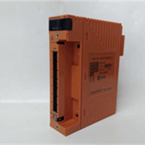
Pneumatic control valves don’t care about your fancy digital networks; they just need clean, accurate air pressure. That’s exactly where the YOKOGAWA PK-200-A33 earns its keep on the plant floor. It acts as the critical bridge between your DCS analog outputs and the physical pneumatic actuators that actually move the valves.Honestly, this I/P converter is a workhorse because it doesn’t try to be anything other than exactly what it needs to be. It delivers ±0.5% accuracy and maintains tight ±0.2% linearity without eating up your plant air budget. It sips only 4 NL/min while capable of outputting 110 NL/min. I’ve seen cheaper converters fail from vibration or moisture in months, but the PK-200’s stainless steel internals and epoxy coating actually hold up in harsh environments. Just don’t expect it to be smart; it’s a dumb, reliable mechanical translator.

Quality SOP & Tech Pitfalls (The Reality Check)
Before this unit leaves our bench, it goes through a strict validation process. We start with a visual and counterfeit check against OEM documentation. Then, it gets hooked up to a calibrated test rack where we sweep the 4-20 mA input and verify the 20-100 kPa output using a deadweight tester. We check insulation resistance with a Fluke 115 multimeter, log the serial number, and seal it in anti-static packaging.Now, for the brutal truth about installing these: Do not skip the air filtration step. I once walked into a refinery where three PK-200s failed in a week because maintenance used cheap, clogged air filters. Moisture and pipe scale destroyed the internal stainless steel metering components. Another classic mistake? Assuming the zero and span adjustments are set at the factory. They aren’t. You must calibrate it on-site with a precision pressure gauge, or your valve will be off by the time it reaches 50% stroke.
Installation & Configuration Guide
Phase 1: Pre-Installation (Safety & Prep)
- ️ Isolate the Loop: Bypass the controller or place it in manual mode to prevent sudden valve movements.
- ️ Depressurize: Shut off and bleed the instrument air supply to the converter.
- Document: Take a high-resolution photo of the existing tubing routing and electrical connections.
Phase 2: Removal
- Label: Tag the 4-20 mA wires and pneumatic tubing clearly.
- Disconnect: Remove the electrical wires and use two wrenches to break the pneumatic fittings (prevents twisting the housing).
- Unbolt: Remove the mounting hardware and extract the old PK-200-A33.
Phase 3: Installation
- Mount: Secure the new PK-200-A33 using the original hardware. Ensure it is mounted vertically if specified by the manual.
- Wiring: Connect the 4-20 mA wires, observing correct polarity.
- Plumbing: Reconnect the instrument air supply and the output tubing to the actuator. Use Teflon tape or pipe sealant rated for instrument air.
Phase 4: Power-On & Testing
- Pre-Check: Verify all connections are tight before opening the air valve.
- Pressurize: Slowly open the instrument air supply and check for leaks using Snoop or soapy water.
- Calibrate: Apply 4 mA and adjust the ZERO screw until output is exactly 20 kPa. Apply 20 mA and adjust the SPAN screw until output is exactly 100 kPa. Repeat until stable.
- Verify: Step the input signal (4, 8, 12, 16, 20 mA) and confirm the valve stroke matches the HMI.

Compatible Replacement Models
| Model | Compatibility Tier | Notes |
|---|---|---|
| YOKOGAWA PK-200-A33 | Drop-in Replacement | Exact match for current setup. No reconfiguration needed. |
| YOKOGAWA PK-200 | ️ Software Compatible | Hardware identical, but verify suffix code for mounting/thread differences. |
| YOKOGAWA PK-300 | Hardware Mod Required | Newer digital/pneumatic hybrid. Requires new tubing, wiring, and HMI config. |
Frequently Asked Questions (FAQ)
Can I use standard shop air for the supply?
Absolutely not. Instrument air must be dry, oil-free, and filtered to at least 5 microns. Moisture will corrode the internal nozzle and flapper assembly in weeks.Does the PK-200-A33 require external power?
No, it is a passive, self-contained pneumatic device. The 4-20 mA signal provides all the electrical energy it needs to operate the internal torque motor.Why is my output pressure hunting or oscillating?
Check your air supply first. Fluctuating supply pressure or a restricted exhaust vent will cause the relay to hunt. If the air is clean, the nozzle/flapper may be worn or contaminated.Is the A33 suffix critical for replacement?
Yes. The suffix dictates the electrical and pneumatic connection thread types (e.g., NPT vs. Rc/PT). Buying the wrong suffix means you’ll need adapters, which just adds potential leak points.Can I calibrate this myself?
Yes, if you have a calibrated pressure gauge and a precision mA source. It requires adjusting the zero and span screws iteratively. If you don’t have the tools, pay an instrument tech to do it. Bad calibration is worse than no calibration.