 Tel:
Tel:  Email:
  WhatsApp:
 Description
Key Technical Specifications
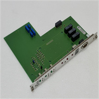
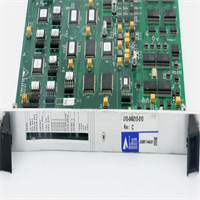
- Part Number: 05701-A-0284
- Board Type: Sensor Interface / Signal Conditioning PCB
- Application Domain: Industrial Fixed Gas Detection (Toxic/Combustible)
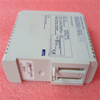
- Mounting: Internal PCB Rack Mount (Chassis specific)
- Input Signal: 4-20 mA / Sensor Bridge (System Dependent)
- Connector Type: Industrial Multi-pin Header
- Voltage Rating: Low Voltage DC (Derived from backplane)
- Environmental Rating: For installation in IP65/IP66 Control Cabinets only
- Status: Obsolete / Legacy Support
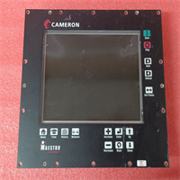
- Compatibility: Specific to older Safegas series control panels

Product Introduction
If you are reading this, you are probably staring at a fault code on a legacy Safegas gas detection panel and realizing that finding spare parts for these older systems is a massive headache. The Sieger 05701-A-0284 is a specific PCB assembly used in these older industrial gas detection systems. I have seen these panels running in oil refineries and chemical plants for over 20 years, silently monitoring for toxic leaks.This board typically functions as the critical link between the field sensors (catalytic bead or electrochemical) and the main system logic. It handles the raw signal conditioning, ensuring that a tiny change in sensor resistance gets translated into an accurate gas concentration reading. There is no fancy firmware to debug here; it is analog hardware at its core. If this board fails, your system is flying blind in a hazardous area, making a verified working spare an absolute necessity for maintaining site safety compliance.
Quality SOP & Tech Pitfalls (The Reality Check)
The Lab Report (SOP):
Because this is a legacy analog interface board, our testing focuses on electrical integrity rather than complex software diagnostics. Before shipping, we:
- Visual Inspection: We examine the PCB under magnification for burnt traces, cracked solder joints, or any signs of corrosion on the connector pins.
- Continuity & Resistance Check: Using a Fluke multimeter, we verify continuity across the primary signal paths and ensure there are no short circuits between the power rails and ground.
- Component Verification: We check that all onboard resistors, capacitors, and op-amps match the expected values and show no physical signs of thermal stress.
- Packaging: The board is sealed in a high-quality anti-static bag with ample bubble wrap to survive rough industrial shipping.
The Engineer’s Warning (Pitfalls):
Here is a brutal reality about these older gas detection boards: Do not assume the board is dead just because the channel is faulting. I have seen countless technicians rip out perfectly good interface boards like the 05701-A-0284, only to find out later that the real culprit was a water-damaged field sensor or a corroded terminal block in a junction box 500 meters away. Before you swap this PCB, use a multimeter to check the loop resistance and voltage coming in from the field. If you install a new board onto a shorted field circuit, you will just blow the new board instantly.
Installation & Configuration Guide
Replacing an internal PCB in a hazardous area control panel requires strict adherence to safety protocols. Follow these steps to ensure a safe swap.
- Pre-Installation:
- ⚠️ SAFETY FIRST: If the panel is in a hazardous zone, ensure you have a valid work permit. Shut down the control panel and isolate the main power supply. Wait 5 minutes for internal capacitors to discharge.
- Take a clear photo of the existing wiring and the board’s position in the rack.
- Removal:
- Carefully disconnect the multi-pin headers and any ribbon cables. Do not pull on the wires—pull by the plastic connector housing.
- Unscrew the mounting hardware or release the DIN rail clips securing the PCB.
- Installation:
- ⚠️ CRITICAL: Compare the new 05701-A-0284 board side-by-side with the old one. Ensure the revision number matches exactly.
- Seat the new board firmly in the chassis and reconnect all interface plugs, ensuring they click securely into place.
- Power-On & Testing:
- Restore the main power to the gas detection panel.
- Observe the boot sequence. If the board is functional, the channel fault should clear. You will likely need to perform a calibration (zero and span) on the associated gas channel using standard calibration gas.
Compatible Replacement Models
Since this is a highly specific legacy spare part, your options are extremely limited.
- ✅ Drop-in Replacement: Sieger 05701-A-0284. This is the exact board. Ensure the suffix matches, as even minor revision changes in legacy gas systems can alter the signal conditioning.
- ⚠️ Verify Compatibility: Sieger 05701 Series (Generic). Other boards in the 05701 series may look physically identical. Do not buy these unless you have physically verified the pinout and component layout match your chassis.
- ❌ Hardware Mod Required: Modern digital gas controllers. You cannot replace this analog legacy board with a modern digital controller without completely rewiring the cabinet and replacing all field sensors, which is a massive engineering project.
Frequently Asked Questions (FAQ)
Q: Is this the main CPU or power supply board for the Safegas panel?
A: No. The 05701-A-0284 is strictly a sensor interface or signal conditioning module. The main processing logic and power supply will be on separate, larger PCBs within the same chassis.Q: My old board looks identical but has a slightly different revision letter. Will this work?
A: Be very careful. In legacy gas detection systems, a minor revision change can mean a different calibration curve or pinout. Always try to match the full part number (05701-A-0284) exactly. If you must use a different revision, consult the OEM wiring diagram first.Q: Does this board require any firmware updates after installation?
A: No. This is an analog hardware interface board. It does not contain user-upgradable firmware. Once it is physically installed and wired correctly, it is ready to process sensor signals.Q: What happens if I install this and the gas reading is still inaccurate?
A: If the new board doesn’t fix the reading, your issue is likely the field sensor itself, which may have reached the end of its lifespan (typically 2-3 years for electrochemical sensors). Try calibrating the channel first; if it won’t calibrate, replace the field sensor.Q: Can I return this if it doesn’t fix my system fault?
A: We stand by our parts. However, please ensure you have properly diagnosed the system before installation. If the board is physically installed and shows signs of electrical damage from an external short circuit, warranty claims may be voided. Always check your field wiring for shorts before powering up.