 Tel:
Tel:  Email:
  WhatsApp:
 Description
Product Introduction
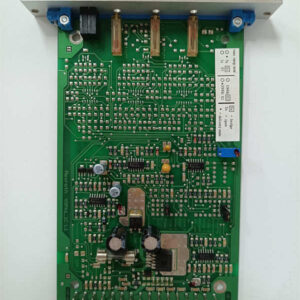
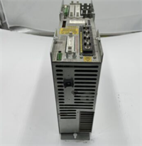
In large-scale automation lines or CNC machines, frequent acceleration and deceleration of servo motors generate massive amounts of regenerative energy. If not handled properly, this can fry the drives and cause grid voltage fluctuations. The Rexroth HVR03.2-W045N is a classic power supply regenerative feedback module from the Bosch Rexroth IndraDrive series. It not only provides a stable DC bus voltage for the entire drive system but also “pushes” the excess energy generated during motor braking back into the grid—saving energy and preventing headaches.Frankly speaking, this power module has incredibly strong overload resistance. Its 45A rated current is more than enough to handle the instantaneous power demands of multi-axis servo systems. In real-world projects, many machines suffer from frequent “DC bus overvoltage” faults simply because they skipped this module. After installing it, the system runs stably, and the heat dissipation pressure in the electrical cabinet drops significantly. For maintenance engineers, having one of these in the spare parts cabinet brings a lot of peace of mind.
Key Technical Specifications
- Material Number (R-number): R911190005
- Rated Current: 45 A
- Compatible System: Rexroth IndraDrive Servo Drive Systems
- Core Function: DC Bus Power Supply & Regenerative Energy Feedback
- Mounting Type: Cabinet wall-mount / Rail mounting
- Cooling Method: Forced air cooling
- Protection Class: IP20 (Installed inside control cabinet)
- Communication Interface: Internal DC bus connection
- Certification Standards: CE, UL
- Country of Origin: Germany / Global (Subject to actual product label)
Installation & Wiring Guide
Stage 1: Preparation (Estimated time: 15 minutes)
- Safety Confirmation: Cut off the main incoming power supply to the entire cabinet and hang a “Do Not Close” warning sign.
- Tool List: Prepare a Phillips screwdriver, torque screwdriver, multimeter, and an anti-static wrist strap.
- Data Check: Find the electrical schematic of the cabinet in advance to confirm the exact location and terminal numbers of the HVR03.2-W045N.
Stage 2: Removing the Old Module (Estimated time: 20 minutes)
- ⚠️ Power-off Operation: Use a multimeter again to confirm that the DC bus voltage has dropped to a safe range (<36V).
- Label Cables: Use label paper to mark the corresponding positions of the incoming lines (L1/L2/L3), DC bus (DC+ / DC-), and ground wires.
- Take Photos: Take high-definition photos of the old module’s wiring terminals, DIP switches (if any), and installation position.
- Removal: Unscrew the fixing bolts and carefully pull out the old module (be careful, the DC bus copper bars can be tight—don’t force them).
Stage 3: Installing the New Module (Estimated time: 25 minutes)
- ESD Protection: Wear an anti-static wrist strap to prevent static electricity from damaging internal electronic components.
- Configuration Replication: Take out the photos you just took and verify that the material number (R911190005) and any DIP switch settings on the new module match the old one.
- Insert into Rack: Align the new module with the mounting holes, tighten the fixing bolts evenly, and ensure good contact between the module and the cabinet backplate (helps with heat dissipation).
- Restore Wiring: Strictly follow the labels to connect the incoming lines and DC bus, and ensure the shielding and ground wires are reliably connected (this is key to anti-interference).
Stage 4: Power-on Testing (Estimated time: 30 minutes)
- Pre-power Check: Use a megger to simply test the insulation resistance at the incoming line terminals to ensure there is no short-circuit risk.
- Indicator Check: After closing the switch and powering on, observe the LED indicators on the module panel. Under normal conditions, the power light should be solid on, with no red fault lights flashing.
- Functional Verification: Use the control panel or host computer to check if the DC bus voltage is stable within the normal range (usually around 560V DC or 700V DC, depending on the specific system).
- Troubleshooting: If a “DC bus undervoltage” alarm occurs, check the incoming line fuses and wiring; if an “overtemperature” alarm occurs, check if the cooling fan is running normally.