 Tel:
Tel:  Email:
  WhatsApp:
 Description
Key Technical Specifications
| Parameter | Specification |
|---|---|
| Manufacturer | National Instruments (NI) |
| Product Type | Fiber Optic GPIB Extender |
| Max Transmission Distance | 1 km (Single Mode Fiber) |
| Data Transfer Rate | Up to 2.8 MB/s (HS488) |
| Bus Compatibility | IEEE 488.1 / IEEE 488.2 |
| Max Devices | 26 (Expanded from standard 15) |
| Interface | GPIB (IEEE 488) to Fiber Optic |
| Signal Integrity | Maintains handshake and data lines |
Product Introduction
The NI GPIB-140A/2 solves the 20-meter cable length restriction imposed by the IEEE 488 standard. In large-scale test environments—such as semiconductor manufacturing or distributed data acquisition systems—equipment is often spread across wide areas. This module acts as a transparent bridge, converting electrical GPIB signals into optical signals. This allows you to place instruments up to 1 kilometer away from the controller while maintaining full bus functionality.Unlike copper cables, which suffer from electromagnetic interference (EMI) and ground loop issues over long runs, the fiber optic connection provides total electrical isolation. This ensures data integrity even in electrically noisy industrial settings. The unit supports high-speed data transfer rates up to 2.8 MB/s using the HS488 protocol. It also expands the system capacity, allowing up to 26 devices on a single bus segment instead of the standard limit of 15.
Installation & Configuration Guide
Preparation
Ensure you have the NI GPIB-140A/2 unit, a compatible power source, and the appropriate fiber optic cables (typically multi-mode or single-mode depending on distance requirements). You will also need standard GPIB cables to connect the unit to your instruments.Removal (if replacing existing hardware)
Power down the system completely. Disconnect the GPIB cables from the old interface card or extender. If removing a rack-mount unit, unscrew the mounting brackets and slide the unit out. Check the backplane connections for any wear.Installation
- Mounting: Secure the GPIB-140A/2 in a location accessible to both the instrument cluster and the fiber network.
- GPIB Connection: Connect the GPIB port of the extender to your test instruments using standard shielded GPIB cables. Keep these local cable runs short (under 2 meters) to reduce noise pickup at the source.
- Fiber Connection: Plug the fiber optic cable into the optical port on the extender. Route this cable to the remote controller or the matching extender unit on the other end.
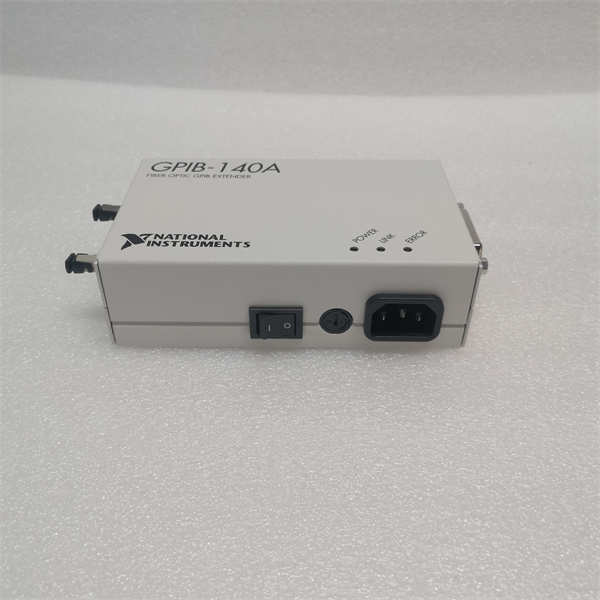
Power-On & Test
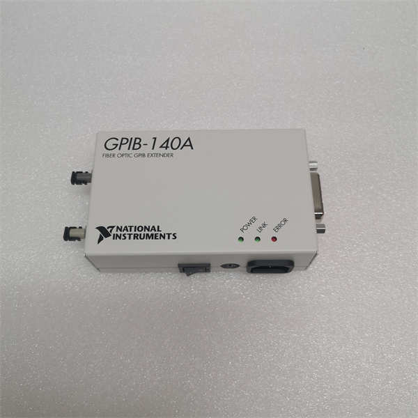
Apply power to the unit. Verify the status LEDs indicate a valid link. In your software (e.g., NI MAX), the device should appear as a standard GPIB interface. Run a simple “Read ID” command on a connected instrument to verify the handshake across the fiber link.
Troubleshooting Quick Reference
| Problem | Probable Cause | Corrective Action |
|---|---|---|
| Link LED is OFF | Fiber cable break or mismatch | Check fiber polarity; verify cable type (single vs. multi-mode). |
| Timeout Error | Address conflict | Ensure no two devices share the same primary address (0-30). |
| Data Corruption | EMI on local copper cables | Replace the short copper patch cables connecting the unit to the instrument. |
| Device Not Found | Bus termination issue | Check if the extender or the last device needs termination enabled. |
| Slow Transfer | Protocol mismatch | Verify HS488 is enabled in the NI-488.2 driver settings. |
Dimensions, Mounting & Wiring Notes
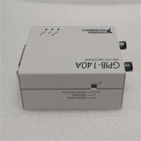
The unit typically features a compact, industrial-grade chassis suitable for rack mounting or benchtop use.
- Mounting: Uses standard screw-hole patterns for secure installation in test racks.
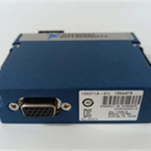
- Connectors: Shielded Centronics-style connector for GPIB; optical ports (often ST or SC type) for the fiber link.
- Wiring Note: While the fiber link is immune to interference, the short copper GPIB cable connecting the extender to the instrument is not. Keep this specific cable run as short as possible.
GPIB-140A 2 NI
FAQ
Can I use this with my existing LabVIEW code?
Yes. The NI GPIB-140A/2 is “software transparent.” Your existing code sees it as a standard GPIB port. You do not need to rewrite commands or change the logic in LabVIEW or LabWindows/CVI.What is the actual distance limit?
You can extend the bus up to 1 kilometer. This is a hard limit determined by the optical transceivers and signal timing constraints of the IEEE 488 protocol.Does this increase the device count limit?
Yes. Standard GPIB is limited to 15 devices (plus the controller). This extender allows you to connect up to 26 devices on the extended bus segment.I’m getting ground loop errors. Will this fix it?
Yes. Because it uses fiber optics, there is no electrical continuity between the controller side and the instrument side. This effectively breaks ground loops that cause noise or equipment damage.Is this unit new or refurbished?
Availability varies. We often supply these as “New Surplus” or “Refurbished/ Tested.” Check the specific listing for the condition code.Do I need a specific driver?
You need the NI-488.2 driver installed on the controlling PC. This driver supports the hardware handshaking and protocol management required for the extension.