 Tel:
Tel:  Email:
  WhatsApp:
 Description
Key Technical Specifications
| Parameter | Specification |
|---|---|
| Input Signal | Standard PLC ±10V, 4-20mA analog |
| Output | Current output compatible with Moog Valves |
| Function | Signal amplification and buffering |
| Filter | Input noise filter with switch-selectable time constant |
| Compatibility | Interfaces Mechanical Feedback (MFB) to Electronic Feedback (EFB) |
| Application | Robotics, CNC, Packaging Machinery |
| Condition | New Surplus / Tested (Verify availability) |
| Origin | Germany / USA (Verify label) |
Product Introduction
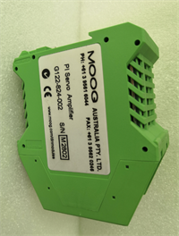
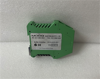
The MOOG G123-825-001 is a high-performance servo amplifier and buffer interface designed for industrial automation. It acts as a bridge between standard PLC analog outputs (±10V or 4-20mA) and Moog servo valves. Its primary utility lies in modernizing machinery: it allows older Mechanical Feedback (MFB) valves to be replaced by modern Electronic Feedback (EFB) valves without requiring a complete overhaul of the existing servo amplifier system.This unit features a built-in input filter to remove signal noise, ensuring stable operation in electrically noisy environments. The filter time constant is switch-selectable, allowing you to tune the response to your specific application. It delivers precise current output to the valve, enabling accurate position and speed control for critical motion tasks.
Installation & Configuration Guide
Preparation (10 min)
- Safety First: Ensure the main power to the hydraulic unit and control cabinet is OFF.
- Verify the input signal type from your PLC (Voltage vs. Current).
- Check the valve type; confirm if you are interfacing an EFB valve.
Removal (5–10 min)
- Disconnect the field wiring from the old amplifier terminals.
- Unmount the old unit from the DIN rail or panel.
- Note: Take a photo of the wiring before removal to ensure correct re-connection.
Installation (10 min)
- Mount the G123-825-001 on the DIN rail or designated panel location.
- Connect the PLC analog output to the input terminals (check polarity).
- Connect the Moog valve to the output terminals.
- Critical Step: Set the input filter switch. If the signal is noisy, increase the time constant.
Power-On & Test (10 min)
- Restore power to the system.
- Verify the LED status indicators (if present) show normal operation.
- Send a low-level command (e.g., 10%) from the PLC to verify valve response.
- Check for “hunting” (oscillation); if found, adjust the filter settings.
Troubleshooting Quick Reference
| Symptom | Probable Cause | Corrective Action |
|---|---|---|
| Valve Not Moving | No output current or loose wiring. | Check input signal presence; verify output terminal tightness. |
| Oscillation / Hunting | Filter time constant too low. | Increase the filter time constant via the dip switch. |
| Incompatible Signal | Wrong input setting (V vs mA). | Verify the jumper/setting matches the PLC output type. |
| Noisy Operation | Electrical interference. | Ensure shield cables are grounded properly at one end. |
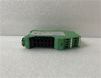
Dimensions, Mounting & Wiring Notes
- Mounting: Typically DIN rail mount or panel mount (verify specific bracket requirements).
- Wiring: Use shielded twisted pair cables for analog inputs to prevent noise.
- Connections: Input is typically ±10V or 4-20mA; Output is current drive for the valve coil.
- Note: The unit acts as a buffer; ensure the power supply capacity matches the valve coil requirements.
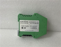
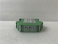
G123-825-001 MOOG
FAQ
What is the main purpose of the G123-825-001?
It amplifies control signals for servo valves. Specifically, it is often used to upgrade systems by allowing modern Electronic Feedback (EFB) valves to work with older control setups.Can I use this with a standard PLC?
Yes, it is designed to accept standard analog outputs (±10V or 4-20mA) directly from a PLC.Is the G123-825-001 the same as IN123-825-001?
The IN123-825-001 is often listed as a newer or equivalent model. The G123-825-001 is the legacy part number. Verify compatibility with your supplier if substituting.How do I reduce noise in the system?
This unit has a built-in input filter. You can adjust the time constant using the switches on the device to smooth out noisy input signals.Does this unit support encoders?
While some references mention encoder modules (like CD522) in the same context, the G123-825-001 is primarily a servo amplifier/buffer. Verify if you need a separate encoder interface module for position feedback.