 Tel:
Tel:  Email:
  WhatsApp:
 Description
Key Technical Specifications
| Parameter | Specification |
|---|---|
| Manufacturer | Mitsubishi Electric |
| Module Type | High-Speed Counter (HSC) |
| Series | FQ Series |
| Inputs | 4 channels (High-speed counter inputs) |
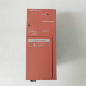
| Input Voltage | 230V AC |
| Mounting | DIN-rail (Standard IEC 60715) |
| Dimensions | 120mm (W) x 100mm (H) x 75mm (D) |
| Communication | Mitsubishi Q/L Series PLCs (via I/O Link) |
| Operating Temp | 0°C to 55°C (32°F to 131°F) |
Product Introduction
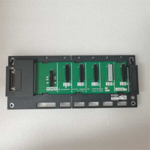
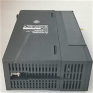
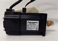
The Mitsubishi HC-KFS23K-S49 is a high-speed counter (HSC) module designed for the FQ series of programmable logic controllers (PLCs). It is engineered to handle rapid pulse inputs, making it ideal for applications requiring precise measurement of frequency, speed, or position.Featuring 4 independent high-speed counter inputs, this module can accurately capture data at rates that standard PLC inputs cannot match. It operates on 230V AC power and connects directly to Mitsubishi’s Q or L series PLCs via the FQ I/O link network. The module is DIN-rail mountable, ensuring a secure and organized installation within an industrial control panel.
Installation & Configuration Guide
Preparation (10 min)
- Power Down: Turn off the main power supply to the control panel. Use a voltage tester to confirm no live circuits are present.
- Mounting Rail: Ensure the DIN rail in the control panel is clean and free of debris. The HC-KFS23K-S49 uses standard IEC 60715 mounting clips.
- ESD Protection: If working in a dry environment, wear an anti-static wrist strap connected to a grounded point to prevent damage to the module’s electronics.
Removal (5–10 min)
- Cable Disconnection: Loosen the terminal screws on the front of the module. Carefully disconnect the wiring (high-speed input signals and power) to prevent strain on the solder joints.
- Release Latch: Press the release latch on the side of the module (if equipped) or gently pry it off the rail using a flat-head screwdriver.
- Storage: Place the removed module in an anti-static bag for storage or transport.
Installation (10 min)
- Align: Slide the module onto the DIN rail. Ensure the mounting clips engage securely with the rail.
- Lock: Press down firmly until you hear a distinct “click,” indicating the module is locked in place.
- Wiring: Connect the wires to the terminal block.
- Input 1-4: High-speed pulse signals (Source/Sink compatible).
- L+/N: 230V AC power supply.
- Shield: Connect the cable shield to the grounding terminal if using shielded cables.
Power-On & Test (10 min)
- Visual Check: Inspect the front panel for any physical damage or loose connections.
- Power Up: Restore power to the control panel.
- LED Indicators: Monitor the status LEDs:
- RUN/ALM: Green indicates normal operation; red indicates a fault (e.g., overvoltage or wiring error).
- IN1-4: Blinking indicates active input pulses.
- PLC Configuration: Verify the PLC recognizes the module on the network and that the counter values increment correctly during operation.
Troubleshooting Quick Reference
| Symptom | Probable Cause | Corrective Action |
|---|---|---|
| ALM Light ON | Overvoltage or wiring error | Check the 230V AC power supply voltage. Ensure no wires are touching adjacent terminals. |
| No Counting | Input signal too slow | High-speed counters require fast pulses. If the signal is too slow, the PLC’s standard input may be needed. |
| Intermittent Counts | Electrical noise | Use shielded cables and ensure the shield is grounded at both ends. Install ferrite chokes on the input wires. |
| Communication Error | PLC network issue | Verify the FQ I/O link cable is securely connected. Check the PLC’s network settings and module address. |
Dimensions, Mounting & Wiring Notes
- Form Factor: DIN-rail mountable (Standard IEC 60715)
- Dimensions: 120mm (Width) x 100mm (Height) x 75mm (Depth)
- Mounting: Secure the module to a 35mm DIN rail using the side clips. Do not overtighten the terminal screws; use 0.5 N·m torque.
- Wiring Notes: The input terminals accept 230V AC signals. Ensure the source/sink configuration matches the module’s internal settings (set via DIP switches or PLC parameter).
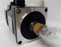
HC-KFS23K-S49 MITSUBISHI
FAQ
Can I use the HC-KFS23K-S49 with a Mitsubishi FX3U PLC?
No, this module is specifically designed for the Q/L series of Mitsubishi PLCs and uses the FQ I/O link network. It is not compatible with the older FX series.What is the maximum counting frequency?
The HC-KFS23K-S49 can handle input frequencies up to 200 kHz per channel, depending on the input type (source or sink) and the PLC’s processing speed.Do I need to set DIP switches on the module?
Yes, the HC-KFS23K-S49 typically requires DIP switch settings to define the input type (source/sink) and the counter mode (up/down, etc.). These settings must match the PLC configuration.Is this module hot-swappable?
No, the HC-KFS23K-S49 is not hot-swappable. You must power down the entire control system before removing or inserting this module to prevent damage to the PLC or the module itself.What is the difference between the HC-KFS23K-S49 and the HC-KFS23K-S48?
The primary difference is the input voltage. The “-S49” version operates on 230V AC, while the “-S48” version operates on 24V DC. The “-S49” is used for industrial applications where 230V AC sensors are standard.
Mitsubishi HC-KFS23K-S49 High-Speed Counter Module