 Tel:
Tel:  Email:
  WhatsApp:
 Description
In-Depth Product Introduction
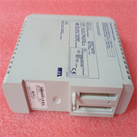
The MDB MLSI-DR11-W (and its upgraded version, the MLSI-DR11-W PLUS) is a classic industrial data acquisition and interface module launched by MDB Systems. On an automation production line, it primarily acts as a “translator,” responsible for signal conversion and data interaction between different industrial control systems or boards, ensuring smooth communication between legacy equipment and modern control systems.Honestly, interface cards like this are becoming incredibly hard to find on the market today. Once this small board fails on a production line that has been running for over a decade, the entire system could face a complete shutdown. For maintenance engineers, finding a pristine original spare part with zero pin oxidation means avoiding the massive costs and long downtime associated with redesigning adapter boards or overhauling the entire production line. Its value lies not in complex computing, but in that irreplaceable compatibility.
Key Technical Specifications
- Interface Standard: DR11-W / DR11-W PLUS
- Product Type: Industrial Data Acquisition & Communication Module
- Compatible Systems: Compatible with various industrial control hosts and backplanes
- Operating Temperature: 0°C to 60°C (Industrial Standard)
- Storage Temperature: -40°C to 85°C
- Protection Rating: IP20 (Must be installed inside a control cabinet)
- Mounting Method: Board Slot / DIN Rail Mount (Depends on the specific backplane)
- Warranty Period: 12 Months
Installation and Wiring Guide
Replacing this type of industrial interface board doesn’t involve high voltage, but it does deal with precision signals, so extra care is needed. Please strictly follow the process below to ensure it powers up on the first try.Phase 1: Preparation (Estimated time: 20 minutes)
- Safety Confirmation: Perform the Lockout/Tagout (LOTO) procedure and cut off the main power supply to the control cabinet. Although the board itself doesn’t run on high voltage, hot-swapping is strictly prohibited to ensure the safety of the backplane and surrounding equipment.
- Tool Preparation: Prepare an anti-static wrist strap, a Phillips screwdriver, a multimeter, and a camera (for recording jumper settings).
- Environment Check: Ensure the control cabinet is dry and dust-free, and check the backplane slots for any debris or bent pins.
Phase 2: Removing the Old Module (Estimated time: 15 minutes)
- Photo Documentation: This step is crucial! Before touching anything, be sure to take multi-angle photos of all jumpers, DIP switches, and external terminal blocks on the old board.
- Disconnect: Loosen the mounting screws and gently unplug all ribbon cables and terminal wires connected to the board.
- Remove Module: Smoothly pull the old board out of the slot or off the rail, and place it on an anti-static mat.
Phase 3: Installing the New Module (Estimated time: 20 minutes)
- ESD Protection: Put on an anti-static wrist strap and take the new MDB MLSI-DR11-W module out of the anti-static bag.
- Configuration Replication: Pull out the photos you just took and verify and set the jumpers and DIP switches on the new board one by one. Many communication failures are simply caused by a single misplaced jumper cap here.
- Insert and Mount: Align with the slot or rail, smoothly push the new module in until the gold fingers make full contact, and then tighten the mounting screws.
- Restore Wiring: Based on your previous markings and photos, accurately reconnect all cables to their corresponding terminals.
Phase 4: Power-On Testing (Estimated time: 30 minutes)
- Pre-Power Check: Visually inspect the board surface again to ensure there are no foreign objects, no loose wires, and confirm the jumper settings are correct.
- Power-On Self-Test: Close the switch to supply power and observe the power indicator light on the board (usually labeled PWR or Power) to see if it lights up normally (typically green).
- Function Verification: Send test commands via the host computer or main control system to check if data acquisition is accurate and if the communication handshake is successful.
- Troubleshooting: If the indicator light doesn’t turn on or communication fails, immediately cut the power. Re-check the jumper settings and verify that the direction of the ribbon cables hasn’t been reversed.
Technical Pitfall Guide
- Jumper Setting Trap: Under the DR11-W standard, different host systems might have slightly different jumper requirements. Never blindly set them based on experience—always use the physical state of the old board as your ultimate guide.
- Electrostatic Discharge (ESD): The chips on these older boards are extremely sensitive to static electricity. If you don’t wear an anti-static wrist strap while working in a dry winter environment, you could easily zap the new board without realizing it, leaving it completely unresponsive when powered on.
- Ribbon Cable Direction: When connecting ribbon cables, pay close attention to the direction of the red wire (Pin 1). Plugging it in backwards might just cause a communication failure at best, but at worst, it could instantly fry the driver chips on the board.