 Tel:
Tel:  Email:
  WhatsApp:
 Description
Key Technical Specifications
| Parameter | Specification |
|---|---|
| Module Type | Communication / Coupling Interface |
| Architecture | Triple Modular Redundancy (TMR) Compatible |
| Safety Rating | SIL 3 (IEC 61508), TÜV Certified |
| Protocols | Profibus DP, Ethernet/IP (Config dependent) |
| Data Integrity | CRC Checksums, Sequence Monitoring |
| Processor | High-performance µC with Watchdog |
| Memory | 1 MB Flash / 1 MB SRAM (Typical for series) |
| Isolation | Galvanic Isolation (Field to Logic) |
| Power Input | 24V DC (Supplied via Backplane) |
| Operating Temp | -20°C to 60°C |
| Enclosure | IP54 (Ruggedized Cast Housing) |
| Dimensions | Approx. 120mm x 80mm (Module only) |
Product Introduction
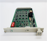
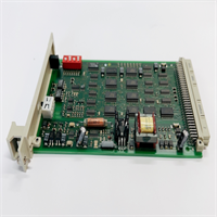
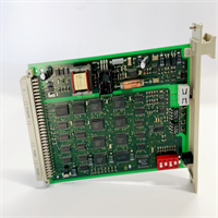
When you are dealing with Emergency Shutdown (ESD) systems, “communication” isn’t just about data—it’s about survival. The HIMA F7533 is a coupling and communication module designed for the HIMatrix safety system. Its job is to act as the secure gateway between your safety logic solver (the CPU) and the outside world—whether that’s a Profibus network controlling turbine valves or an Ethernet link to a DCS.This isn’t a standard PLC comms card. It is built for Triple Modular Redundancy (TMR) environments. This means it can operate in a system where three processors are voting on every decision. If one processor (or even this communication module) detects a fault, the system masks it and keeps running without tripping the plant. I’ve seen these modules sitting in refineries for 15 years, handling critical fire and gas detection signals. They are bulletproof, but they are also “smart.” They don’t just pass bits; they validate them. If the data integrity fails the safety check, the module blocks it. That’s the difference between a process stop and a catastrophic failure.
Quality SOP & Tech Pitfalls (The Reality Check)
The Lab Report (SOP)
We verify the intelligence of the card, not just the power.
- Visual Inspection: We check the housing seals (IP54 rating). In safety systems, dust ingress can cause static discharge failures. We also inspect the backplane pins for “wipe marks” indicating poor insertion history.
- Protocol Handshake Test: We connect the module to a HIMA test rack. We simulate a Profibus master and force the F7533 to exchange data packets. We verify that the “Watchdog” signal toggles correctly.
- Redundancy Simulation: We run a test where we artificially corrupt data packets. The F7533 must detect the corruption and flag the error bit within milliseconds. If it passes bad data, it fails the test.
- Firmware/Version Check: We verify the internal revision. HIMA is strict about firmware matching in redundant pairs.
The Engineer’s Warning (Pitfalls)
- The “Slave” Address Conflict: Like many industrial comms cards, the F7533 uses hardware switches (DIP or rotary) to set the node address. If you swap the card and forget to reset the address, or if you accidentally bump a switch during installation, the safety controller will lose communication with the field devices immediately. Verify the address before you seat the card.
- Termination Errors: If this module is used as the last node on a Profibus line, the termination resistor must be engaged (usually via a switch or jumper). If you leave it off, signal reflections will cause intermittent “Comm Fail” alarms that are impossible to troubleshoot remotely.
- Field Disaster: A technician replaced a faulty F7533 but didn’t realize the system was running in “Force Mode.” When the new card initialized, it cleared the forced values. The safety logic instantly saw a “low-low” level in a separator vessel and initiated a full platform shutdown. Always check for active forces before swapping safety hardware.
Installation & Configuration Guide
Precision is non-negotiable here. This is a safety component.
- Pre-Installation Safety
- ⚠️ CRITICAL: Place the safety logic in “Maintenance Mode” or override the relevant trip votes. Swapping a comms card breaks the link to the field devices, which the CPU might interpret as a “wire break” or “fail-safe” condition.
- Photograph the DIP switches and jumpers on the old module. This is your configuration map.
- Removal
- Disconnect the fieldbus cables (DB9, RJ45, or terminal block). Label them clearly (e.g., “Port A – To Turbine”).
- Release the locking lever/screw on the module faceplate.
- Slide the module out of the HIMatrix carrier.
- Hardware Setup
- Place the new F7533 on an anti-static mat.
- Configure Hardware: Set the DIP switches/jumpers to match your photos exactly. Pay attention to “Termination” and “Baud Rate” settings.
- Insert the module into the slot. Push firmly until the backplane connector seats fully. Lock the mechanism.
- Power-Up & Commissioning
- Reconnect the cables.
- Remove the maintenance bypass.
- Watch the LEDs. You want to see the “Run” LED solid green and the “Com” LED blinking (indicating traffic).
- Verify the “System OK” status in the HIMA engineering software (SILworX or similar).
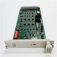
F7533 HIMA
Compatible Replacement Models
- ✅ Drop-in Replacement: F7533. This is the exact model. Suffix variations (like revision numbers) are generally compatible, but verify with the datasheet.
- ⚠️ Functional Equivalent: F8621A. This is another HIMA communication module (often RS485/Modbus). It fits the same slot but serves different protocols. Do not use unless you are migrating the network protocol.
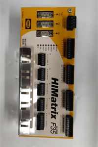
- ❌ System Upgrade: HIMatrix F60 CPU. Newer HIMA systems integrate communication directly into the CPU or use different form factors (F60/F35). Migrating requires a full rack change.
Frequently Asked Questions (FAQ)
Q: Can I hot-swap this module?
A: Technically, the HIMatrix system supports hot-swapping. However, because this is a communication coupler, pulling it breaks the link to the field devices. Unless you have a redundant pair (two F7533s running in parallel), removing the active card will likely cause a communication fault alarm or a trip.Q: My “Error” LED is flashing red. What does it mean?
A: On HIMA safety modules, a red LED usually indicates an internal diagnostic failure or a mismatch with the controller’s expected configuration. Check that your DIP switch settings (address/baud) match the project configuration exactly.Q: Does this support Ethernet?
A: The F7533 is typically associated with serial fieldbuses like Profibus. If you need Ethernet/IP or Modbus TCP, you are likely looking for a newer module like the F8650E or a specific Ethernet variant of the HIMatrix series.Q: Why is this module so expensive?
A: You are paying for the safety certification. This isn’t just a plastic chip; it’s a TÜV-certified device capable of operating at SIL 3 levels. It undergoes rigorous manufacturing testing to ensure it fails safely.Q: What is the difference between F7533 and F7534?
A: These numbers usually denote different revisions or specific protocol loadings (e.g., one optimized for Profibus, another for a specific Ethernet variant). Always check the part number suffix on the label.