 Tel:
Tel:  Email:
  WhatsApp:
 Description
⚙️ Key Technical Specifications
| Parameter | Specification | Notes |
|---|---|---|
| Input Voltage | 24 V DC (Nominal) | Range: 19.2 – 30 V DC |
| Output Channels | 4 Discrete Channels | Independently fused |
| Max Current | 4 A per channel | Continuous load rating |
| Fuse Type | Micro-Blade / Miniature | User replaceable |
| Switching Time | ~100 ms (Relay logic) | Fast fault isolation |
| Residual Voltage | < 0.5 V | Minimal voltage drop |
| Protection | Short Circuit / Overload | Per-channel monitoring |
| Status Indicators | 4x Green LEDs (Channel OK) | Visual troubleshooting |
| Mounting | DIN Rail (35mm) | Standard industrial rail |
| IP Rating | IP20 (Module) | Touch-safe terminals |
| Operating Temp | -20°C to +60°C | Derate at high altitude |
| Dimensions | 4 TE (Eurocard width) | Compact footprint |
👷 Product Introduction
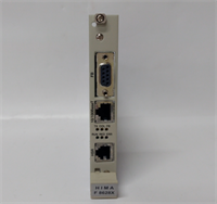
In a safety system, power isn’t just “on” or “off”—it’s about clean, isolated, and protected distribution. The HIMA F7133 is one of those unassuming modules that sits quietly in the rack until you need it to save your bacon. It’s not a processor; it doesn’t run logic. Its job is simpler but critical: take the main 24V supply and break it into four distinct, fused branches for your field instruments.Why do I like this module? Because it kills two birds with one stone: isolation and visibility. If a solenoid valve shorts out on Channel 2, the F7133 blows its internal fuse and lights up an LED. You don’t have to hunt through a bundle of wires with a multimeter, and more importantly, the short doesn’t drag down the voltage for the rest of the I/O rack. It keeps the rest of the system alive while isolating the fault. It’s simple, mechanical, and reliable—exactly what you want in a SIL 3 environment.
🔍 Quality SOP & Tech Pitfalls (The Reality Check)
The Lab Report (SOP)
We don’t trust “New in Box” blindly, especially with power components.
- Visual Inspection: We check the fuse holders. Are they tight? Is there corrosion on the contacts? We also look for cracked solder joints on the terminal blocks.
- Continuity Test: With power off, we measure resistance from Input to each Output. It should be near zero ohms (closed circuit).
- Live Load Test: We apply 24V DC and hook up a resistive load bank. We ramp up the amps to 4A on each channel to ensure the voltage drop stays within spec (<0.5V).
- Fault Simulation: We intentionally short one channel to verify the fuse blows instantly and the LED status changes. If the fuse holds too long, the board goes back.
The Engineer’s Warning (Pitfalls)
Don’t ignore the fuse rating.
The F7133 uses specific micro-fuses. I’ve seen technicians replace a blown fuse with a generic auto-parts fuse or a higher amperage rating because it was “close enough.” That is a fire hazard waiting to happen. If the board trips, find out why before you reset it.
Field Disaster Story: A plant had nuisance trips on an F7133. They kept swapping the module, thinking it was defective. Turns out, the field wiring for a level switch had chaffed against a conduit, creating an intermittent ground fault. The F7133 was doing its job perfectly by blowing the fuse. They replaced the cable, not the module. Always check the field side first.
🛠️ Installation & Configuration Guide
This is hardware, pure and simple. No software configuration is needed, but physical installation matters.
- Pre-Installation (Safety First)
- ⚠️ LOCK OUT / TAG OUT: Kill the 24V DC supply. Even low voltage can arc if you short the busbars.
- Check the Fuses: Before installing, pull the fuses out and check their ratings (usually 4A or similar, marked on the blade). Ensure they match the schematic.
- Removal
- Remove the wiring connectors (Phoenix Contact style usually).
- Unclip the module from the DIN rail. It might be stiff if the rail is dirty.
- Installation
- Clip the new F7133 onto the rail next to the power supply or I/O modules.
- Reconnect the wiring. Torque check: Tighten the terminal screws. Loose power connections cause heat, and heat melts plastic.
- Verify polarity: Input (+) and (-) must be correct. Reverse polarity won’t hurt the passive distribution, but it won’t power your devices either.
- Power-On & Testing
- Restore 24V DC power.
- Check the LEDs. All active channels should show Green.
- Measure output voltage at the terminals with a Fluke meter to confirm you are getting clean 24V DC.
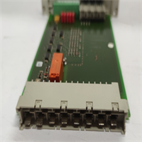
F7133 HIMA
🔄 Compatible Replacement Models
| Model | Compatibility | Notes |
|---|---|---|
| F7133 (984230425) | ✅ Drop-in Replacement | Standard 4-channel PDM. |
| F7130A | ❌ Different Function | This is a Power Supply unit (AC/DC converter), not a distributor. |
| F7126 | ❌ Different Function | Power supply monitor/battery backup module. |
| Z7133 | ✅ Accessory Match | Often refers to the connector/cable kit for the F7133. |
💬 Frequently Asked Questions (FAQ)
Q: My F7133 LED is red (or off). What does that mean?
A: On most revisions, a missing green light means the fuse for that specific channel has blown. Check the fuse physically. If the fuse is good but no light/voltage, the internal relay or trace might be damaged.Q: Can I use this for 120V AC distribution?
A: No. The F7133 is designed for 24V DC distribution. Using it for AC will likely damage the internal components or create a safety hazard. Stick to the datasheet specs.Q: How do I know which fuse to buy?
A: Look at the marking on the existing fuse blade. It will say something like “4A” or “F4A”. HIMA uses standard automotive-style blade fuses or specific miniature industrial fuses depending on the revision. Verify with the manual.Q: Does this module require a firmware update?
A: No. It is a hardware-only device. There is no software, logic, or firmware inside an F7133. It’s strictly electrical distribution.Q: Can I daisy-chain the outputs?
A: You can, but you shouldn’t. The point of this module is isolation. If you jumper the outputs together, you defeat the purpose of having separate fused channels. Keep them separate to isolate faults.