 Tel:
Tel:  Email:
  WhatsApp:
 Description
Key Technical Specifications
| Parameter | Specification |
|---|---|
| Function | Power Supply Monitoring & Diagnostics |
| Input Voltage | 24V DC (Nominal), Range ~18-30V DC |
| Monitoring | Voltage Level, Polarity, Current Draw |
| Alarm Output | Relay Contact (Form C / SPDT typical) |
| Indicators | LEDs for “OK”, “Fail”, “Power” |
| Safety Rating | IEC 61508 SIL 3 (System Capability) |
| Mounting | DIN Rail or HIMA Chassis Slot |
| Weight | Approx. 0.5 – 1.0 kg |
Product Introduction
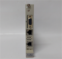
You can have the most sophisticated safety logic in the world, but if the power feeding it fluctuates, you’re flying blind. The HIMA F7131 (981713102) is the unsung hero of the cabinet—the bodyguard that watches the voltage rails so the CPU doesn’t have to. It sits between your bulk power supply and the sensitive logic modules, constantly checking for undervoltage, overvoltage, or polarity reversals.I’ve seen plants trip because a cheap power supply started ripple-noising right before it died. If you don’t have an F7131 monitoring that line, the CPU might latch onto a bad bit and lock up. This module catches those glitches and triggers a safe shutdown before the logic gets corrupted. It’s simple, rugged, and essential for any system claiming SIL 3 integrity. Don’t treat it like a fuse; treat it like a diagnostic tool.
Quality SOP & Tech Pitfalls (The Reality Check)
The Lab Report (SOP)
We don’t just verify continuity on these. A power monitor needs to be accurate.
- Visual Inspection: We check for heat discoloration on the PCB, specifically near the input terminals and relay coils.
- Voltage Threshold Test: We use a calibrated DC power source to ramp the voltage up and down. We verify the “Undervoltage” alarm trips exactly at the spec limit (usually around 18-20V).
- Relay Logic Check: We measure the resistance across the alarm relay contacts. We verify the relay energizes/de-energizes correctly based on the “Good/Bad” status.
- Load Test: We apply a dummy load to ensure the module can handle the current draw without overheating.
️ The Engineer’s Warning (Pitfalls)
Don’t ignore the alarm relay wiring. The F7131 usually has a “fail-safe” relay configuration. This means the relay is energized when things are good, and de-energized (opens/closes) when power fails. If you wire this assuming “Normally Open” without checking the schematic, your safety system won’t know the power is dead until it’s too late.Also, check your ground loops. Since this module monitors voltage levels precisely, a bad ground connection can make the module “think” the voltage is low, causing nuisance alarms. Ensure your chassis grounding is solid before blaming the module.
Installation & Configuration Guide
Phase 1: Pre-Installation
⚠️ Safety First: Disconnect the main 24V DC supply. You are working with live power rails; shorting a screwdriver across the terminals can weld metal instantly.
- Photo Documentation: Take a picture of the terminal wiring. Power wiring mistakes are common and dangerous.
- Verify Source: Ensure your incoming 24V DC source is stable and clean (low ripple).
Phase 2: Removal
- Disconnect the field wiring harness or terminal block screws.
- Release the locking clip or DIN rail latch.
- Pull the module out carefully.
Phase 3: Installation
- Seat the Module: Slide the F7131 into the designated slot or snap it onto the DIN rail.
- Wire It Up: Connect the 24V DC input and the output to the protected load. Double-check polarity (+ vs -).
- Connect Alarm: Wire the alarm relay contacts to your annunciation panel or PLC input.
Phase 4: Power-On & Testing
- Apply power.
- LED Check: The “Power” or “OK” LED should illuminate immediately.
- Simulate Fault: If possible, briefly lower the input voltage to verify the “Fail” LED lights up and the alarm relay changes state.
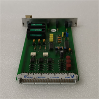
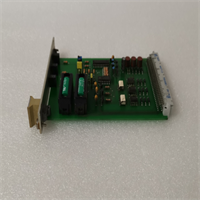
F7131 981713102 HIMA
Compatible Replacement Models
| Model | Compatibility Tier | Notes |
|---|---|---|
| F7131 (981713102) | Exact Match | Standard revision for HIMax systems. |
| F7126 | Different Function | This is typically a Power Supply Unit (PSU), not a monitor. Do not confuse them. |
| F7537 | Variant | Older or different series board. Requires chassis verification. |
Frequently Asked Questions (FAQ)
Q: What is the difference between F7131 and F7126?
A: The F7126 is generally the actual Power Supply Unit that converts AC to DC (or DC-DC). The F7131 is the Monitor that watches that power. You often need both: one to make the power, one to watch it.Q: Does this module provide 24V power?
A: No, not primarily. It passes power through to the load, but its main job is supervision. Do not use it as a substitute for a dedicated power supply unit like the F7126.Q: My “Fail” LED is blinking. What does that mean?
A: This indicates the input voltage has dropped below the threshold (Undervoltage) or risen too high (Overvoltage). Check your main power supply and battery backup. It could also indicate a wiring fault (loose terminal).Q: Is this module hot-swappable?
A: Generally, no. Since it is part of the power distribution chain, removing it will cut power to downstream modules unless you have a fully redundant parallel setup with diodes. Plan for a shutdown.Q: What does “981713102” mean?
A: That is the specific订货号 or manufacturing part number for the F7131 hardware revision. It ensures you are getting the correct circuit board layout for your specific HIMA chassis generation.