 Tel:
Tel:  Email:
  WhatsApp:
 Description
Key Technical Specifications
| Parameter | Specification |
|---|---|
| Input Voltage | 24 V DC (-15% / +20%) |
| Output Voltage | 5 V DC (Adjustable ±0.5V) |
| Output Current | 10 A (Continuous) |
| Current Limit | Approx. 13 A |
| Efficiency | ≥ 77% |
| Overvoltage Protection | Set to 6.5 V ±0.5 V |
| Isolation | Safe isolation between Input and Output |
| Fuse | 6.3 A (Slow-blow/Time-lag) |
| Width | 8 TE (approx. 40mm) |
| Weight | ~0.6 kg |
Product Introduction
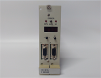
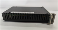
If you’ve ever worked on a HIMA safety system, you know that the “brains” (the CPUs) are useless without clean, stable juice. The HIMA F7126 is that juice. It’s a heavy-duty DC/DC converter that takes your cabinet’s 24V supply and steps it down to a precise 5V to run your logic cards.What makes this module critical isn’t just the conversion; it’s the safety features. It’s designed with safe isolation and overvoltage protection because, in a Safety Instrumented System (SIS), a power spike can cause a spurious trip—or worse, a failure to trip. It handles 10 Amps, which is enough to feed a whole rack of I/O modules. I’ve seen these units run for 15 years without a hiccup, but when they do fail, the whole rack goes dark. It’s a robust unit, but it runs hot, so keep your cooling fans working.
Quality SOP & Tech Pitfalls (The Reality Check)
The Lab Report (SOP)
Before I install an F7126 in a live safety rack, I put it on the bench. Here is my checklist:
- Visual Inspection: Look at the capacitors. Bulging tops mean it’s seen high heat or ripple. Check the adjustment potentiometer—is it stuck or corroded?
- Input Test: Apply 24V DC. Verify the input current draw is within spec (no shorted primary).
- Output Regulation: Measure the 5V output. It should be steady. Use the trim pot to adjust if necessary (Factory default is usually around 5.4V for cable compensation, but check your manual).
- Load Test: Hook up a dummy load. Pull 5A, then 10A. The voltage shouldn’t droop more than a few millivolts.
- Protection Test: If possible, trigger the overvoltage clamp. It should shut down or clamp at 6.5V to protect downstream electronics.
The Engineer’s Warning (Pitfalls)
Here is the mistake that burns people: Parallel Redundancy Mismatch.If you are running redundant F7126 modules (which you should be), their output voltages must be matched perfectly—within 0.025V. If one is set to 5.00V and the other to 5.10V, the higher one does all the work while the other sits idle. When the first one fails, the second one might not pick up the load fast enough, causing a brownout. Always measure and match your outputs before installing them in a redundant pair. Also, watch out for the short-circuit recovery. While it is “short-circuit proof,” repeated shorts can degrade the internal components.
Installation & Configuration Guide
Swapping a power supply is risky business. One slip and you take down the controller.
- Pre-Installation ⚠️
- Backup: Save your logic. Seriously.
- Voltage Check: If replacing one of a redundant pair, measure the output of the good unit. You need to set the new unit to match it exactly.
- Removal
- Disconnect the 24V input wiring.
- Disconnect the 5V output wiring (careful, these are often daisy-chained to the backplane).
- Release the DIN rail clip or screws. Slide out.
- Installation
- Insert the new F7126. Secure it.
- Adjustment: Before connecting the output, apply 24V input. Use a small screwdriver on the front trim pot to set the output to match your system requirement (usually 5.0V – 5.4V).
- Reconnect the wiring. Ensure tight torque on the terminals—loose connections cause voltage drops that look like module failures.
- Power-On & Testing
- Apply 24V.
- Verify 5V output at the module terminals.
- Verify 5V at the backplane/CPU.
- Watch the LEDs on the CPU modules—they should come alive.
F7126 HIMA
Compatible Replacement Models
This is a specific form factor, so stick to the known quantities.
- ✅ Drop-in Replacement: F7126. This is the standard 10A unit.
- ⚠️ Alternative Config: F7130A. Another HIMA power module, but verify the pinout and wattage. Do not assume they are interchangeable without checking the wiring diagram.
- ❌ Not a PSU: F7133. This is a power distribution module (fuse holder), not a voltage converter. Don’t mix them up.
Frequently Asked Questions (FAQ)
Can I adjust the output voltage?
Yes. There is a potentiometer on the front plate. You can adjust it typically between 4.5V and 5.5V. However, for HIMA systems, the sweet spot is often slightly higher (around 5.4V) to compensate for voltage drop across the backplane. Check your system manual.Why is my F7126 getting very hot?
It will run warm (efficiency is ~77%, meaning 23% of power is lost as heat). However, if it’s too hot to touch, check your load. Are you drawing more than 10A? Or is the ventilation in the cabinet blocked? Overheating is the #1 killer of these units.What happens if I exceed 10A?
The module has a current limiter that kicks in around 13A. It will likely fold back the voltage to protect itself. If you need more current, you need to distribute the load across multiple power supplies or use a higher capacity external PSU feeding the 5V rail (if the architecture allows).Is the input fused internally?
It usually requires an external primary fuse (6.3A time-lag is recommended), though some revisions might have internal protection. Always fuse your 24V source.Can I use this for non-HIMA applications?
Technically yes, it’s just a 24V to 5V DC/DC converter. But you are paying a premium for the “Safety” certification and the specific form factor. If you aren’t in a HIMA rack, a standard industrial DIN-rail power supply is cheaper and easier to find.