 Tel:
Tel:  Email:
  WhatsApp:
 Description
Key Technical Specifications
| Parameter | Specification |
|---|---|
| Channels | 16 Independent Digital Inputs |
| Nominal Voltage | 24V DC (Typical range 18-30V DC) |
| Logic Levels | “0” Signal: < 5V DC; “1” Signal: > 15V DC |
| Input Current | Approx. 3-5 mA per channel (Typical) |
| Isolation | Group Isolation or Channel-to-Channel (Check Revision) |
| Response Time | < 10ms (Configurable filtering) |
| Safety Rating | IEC 61508 SIL 3 / Category 4 |
| Diagnostics | Wire break detection, Short circuit monitoring |
Product Introduction
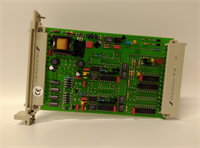
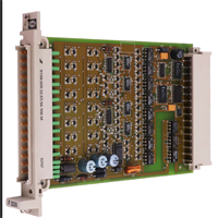
In a safety loop, you can have the best logic solver in the world, but if your input card is blind, you’re flying on instruments that don’t work. The HIMA F3231 is the eyes of the system. It’s a 16-channel digital input module designed to read those critical limit switches and pressure transmitters that tell the CPU whether to trip the turbine or open the valve.I’ve seen these cards sitting in cabinets for 15 years, covered in dust, handling 24V signals without missing a beat. What makes the F3231 different from a standard PLC input card is the internal architecture—it’s built to detect faults like wire breaks or short circuits before they cause a spurious trip. It plays nice with HIMA’s Triple Modular Redundancy (TMR) systems, meaning it can feed three processors simultaneously. If you are maintaining a legacy HIMA system, this card is bread-and-butter.
Quality SOP & Tech Pitfalls (The Reality Check)
The Lab Report (SOP)
We don’t just look at the LEDs. Here is how we validate an F3231:
- Visual Inspection: We check the PCB for corrosion, specifically around the terminal blocks. We also inspect the edge connector pins—bent pins here kill the backplane communication.
- Threshold Test: We use a calibrated power supply to ramp voltage up and down on a test channel. We verify the “ON” threshold triggers reliably around 15V and the “OFF” drops out correctly below 5V.
- Loopback/Diagnostic Check: We simulate a wire break to ensure the module’s internal diagnostics flag the error to the CPU.
- Backplane Comm: We plug it into a test rack to ensure it talks to the HIMA processor without generating bus errors.
️ The Engineer’s Warning (Pitfalls)
Don’t trust the “Common” terminals blindly. On some revisions of the F3231, the inputs are grouped. If you short one common rail because of a wiring error, you might take out half the card’s channels. Always verify your field wiring polarity before snapping the terminal block onto the module.Also, watch out for ground loops. Since these modules often have isolation barriers, connecting the shield of your field cable to both the sensor and the module chassis can create a loop that induces noise. This noise can trick the input into thinking a switch is closed when it’s open. Ground your shields at the cabinet end only.
Installation & Configuration Guide
Phase 1: Pre-Installation
⚠️ Safety First: Turn off the 24V DC field power. While 24V won’t kill you, shorting a live wire across the terminal block can arc and damage the plastic housing.
- Photo Documentation: Take a picture of the existing wiring. Seriously. Do not rely on faded wire markers.
- ESD Prep: Touch the chassis frame. Static electricity can fry the input optocouplers.
Phase 2: Removal
- Disconnect the field wiring harness (usually a screw-terminal block).
- Release the locking mechanism (top and bottom clips).
- Pull the module straight out. If it sticks, check for a stuck latch, don’t pry it.
Phase 3: Installation
- Seat the Module: Slide the F3231 into the slot. You should feel a firm connection with the backplane.
- Wire It Up: Reconnect the wiring based on your photo. Ensure tight connections—loose wires cause intermittent faults that are a nightmare to troubleshoot.
- Lock it Down: Engage the clips.
Phase 4: Power-On & Testing
- Apply power.
- LED Check: Watch the boot sequence. The module LEDs should flash or turn solid green depending on the status.
- Force Test: Close a contact in the field (or short the terminal) and watch the corresponding LED light up. Then verify the status in the software.
F3231 HIMA
Compatible Replacement Models
| Model | Compatibility Tier | Notes |
|---|---|---|
| F3231 | Exact Match | Standard 16-channel input. |
| F3232 | Variant | Often differs in channel count (e.g., 8-channel) or voltage rating. Check datasheet. |
| F3330 | Different Function | This is a Digital Output module. Do not mix them up. |
Frequently Asked Questions (FAQ)
Q: Can I hot-swap this module?
A: Generally, yes. HIMA systems support online replacement of I/O modules. However, pulling the card will momentarily lose the input status for those 16 points. If your logic relies on a “healthy” signal from these inputs, it might trigger a nuisance trip. Bypass the logic first.Q: My LED is red/flashing. What does that mean?
A: On the F3231, a red LED usually indicates a hardware fault or a configuration mismatch with the system database. It could also mean the module has detected a short circuit on the 24V supply rail.Q: Does this support 120V AC inputs?
A: No. The F3231 is strictly a 24V DC module. If you hook up 120V AC to this card, you will destroy the input circuitry instantly. For AC inputs, you need a different model (like the F321x series).Q: How do I know if my revision supports channel-to-channel isolation?
A: Check the manual for the specific part number suffix. Most standard F3231s have group isolation (channels 1-8 share a common, 9-16 share a common), but fully isolated versions exist for high-noise environments.Q: Is this module obsolete?
A: It is considered legacy hardware. While HIMA supports these systems, finding brand-new stock is getting harder. Most available units are surplus or refurbished. If you are doing a full system upgrade, look into the newer HIQuad series, but for a repair, this is what you need.