 Tel:
Tel:  Email:
  WhatsApp:
 Description
Key Technical Specifications
- Manufacturer: General Electric
- Product Type: I/O Board (Analog)
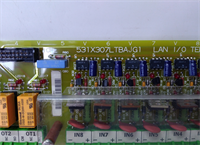
- Control System Series: Mark V
- Board Designation: TCQA
- Signal Inputs: LVDT, Thermocouples, 4-20 mA, Vibration, Voltage
- Signal Outputs: Servo Valve, Relay Driver, 4-20 mA
- Output Current Config: 20 mA or 200 mA (via J5/J6 jumpers)
- Data Bus Connector: 3PL (COREBUS interface)
- Communication Port: RS232 (via J7 for card testing)
- Oscillator Control: J8 Hardware Jumper
- Target Application: Gas Turbine Control Systems

Product Introduction
Gas turbines don’t care about your maintenance schedule; they just run until something breaks. The GE IS200JPDMG1A is the unsung hero inside the Mark V cabinet, quietly taking a messy mix of thermocouple readings, LVDT position feedback, and 4-20 mA pressure signals, and conditioning them so the core processors don’t choke. I’ve seen entire turbine trips traced back to a single fried analog board sending garbage data to the RST core.Engineers keep hunting for this specific TCQA board because ripping out a Mark V cabinet for a Mark VIe upgrade costs hundreds of thousands of dollars. This board handles the dirty work of scaling compressor stall detection signals and fuel flow pressures. Just remember, this board is covered in hardware jumpers. I’ve seen guys plug in a replacement, power up, and immediately trip the unit because they forgot to move the J5 and J6 jumpers to match the 200 mA output range of the old board.
Quality SOP & Tech Pitfalls (The Reality Check)
The Lab Report (SOP)
We don’t just wipe the dust off and ship these. First, we inspect the multi-layer board for cracked solder joints around the heavy JE and 3PL connectors. Next, it goes on a Mark V test rack where we inject simulated 4-20 mA signals and verify the scaling matches OEM tolerances. We check the RS232 port (J7) to ensure diagnostic communication works. Finally, we perform an insulation resistance test and seal it in anti-static packaging. You get a test report, not just a tracking number.The Engineer’s Warning (Pitfalls)
Never ignore the jumper settings. The J1 and J2 jumpers select the milliamp output circuit, and J5/J6 configure the range. If you swap this board and the turbine servo valves start hunting or the fuel valve won’t stroke, 99% of the time it’s a jumper mismatch. Also, treat the RS232 port with respect. I’ve seen techs use a cheap, unisolated laptop USB-to-serial adapter to test the J7 port, and the ground loop instantly blew the opto-isolators on the board. Always use an isolated diagnostic cable.
Installation & Configuration Guide
- Pre-Installation: ⚠️ SAFETY FIRST. Lock out turbine control power. Wait for the Mark V power supply capacitors to discharge. Take high-resolution photos of ALL jumper blocks (J1, J2, J5, J6, J7, J8) and connector pinouts.
- Removal: Label the 3PL data bus, JE communication, and JG vibration cables. Carefully release the board from the I/O core rack. Do not force it; Mark V backplane pins bend easily.
- Installation: Copy the DIP/Jumper settings exactly. This prevents 90% of startup failures. Align the new IS200JPDMG1A and press it evenly into the backplane. Reconnect cables exactly as photographed.
- Power-On & Testing: Restore control power. Watch the core processor LEDs for communication faults on the 3PL bus. Use the RS232 port to run a card-level diagnostic test before allowing the turbine to enter auto-control mode.
Compatible Replacement Models
- ✅ Drop-in Replacement: IS200JPDMG1ACC / IS200JPDMG1ADC. Same hardware footprint and base firmware. Verify the suffix revision to ensure jumper logic is identical.
- ⚠️ Software Compatible: IS200JPDMG1B. Same physical board, but may require a Mark V EEPROM update or parameter reconfiguration in the operator interface. Expect 1-2 hours of commissioning time.
- ❌ Hardware Mod Required: IS220 Series Analog Boards. Completely different architecture. Requires new backplane, rewiring, and a full Mark VIe migration. Do not attempt this as a quick field swap.

Frequently Asked Questions (FAQ)
- Can I hot-swap this analog I/O board?
Absolutely not. The Mark V system does not support hot-swapping core I/O boards. Pulling this while the turbine is running will cause immediate data loss and likely trip the unit. Always schedule a controlled shutdown. - Is this a brand-new original GE part?
GE stopped manufacturing Mark V boards years ago. What we sell is “New Surplus” (factory sealed, never installed) or professionally refurbished. We guarantee it works to OEM specs, but don’t expect shrink-wrap from the 1990s. - What does the JE connector actually do?
The JE connector handles the heavy traffic: pulse signals, generator/line signals, relay driver outputs, and servo valve commands to the TCQC board. If your turbine is tripping on servo faults, check the pins on this connector for corrosion first. - Will this work with my Mark VI system?
No. The IS200JPDMG1A is strictly for the Mark V Speedtronic platform. Mark VI uses a completely different I/O rack architecture. - How do I know if this board is actually bad?
Check the 4-20 mA outputs with a multimeter while commanding a valve stroke. If the board output is flat or erratic but the core processor is commanding the correct value, the board’s DAC circuit is fried. Also, check for 24V DC at the board; no power means no signal. - What if it fails after installation?
We provide a 1-year warranty. If it dies under normal operating conditions, we replace it. But if we find burn marks from a shorted servo valve or a spiked 3PL bus, that’s on you. Always megger test your field wiring before plugging in a new I/O board.