 Tel:
Tel:  Email:
  WhatsApp:
 Description
Key Technical Specifications
| Parameter | Specification |
|---|---|
| Manufacturer | GE Fanuc (General Electric) |
| Product Series | Genius I/O |
| Number of Circuits | 32 (16 Input / 16 Output) |
| Input Voltage | 24 VDC |
| Output Current (Max) | 0.5A per circuit, 16A total |
| Dimensions (H×W×D) | 112 mm × 90 mm × 224 mm |
| Weight | 1.8 kg (4 lbs) |
| Operating Temperature | 0°C to 60°C |
Product Introduction
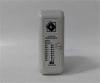
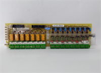
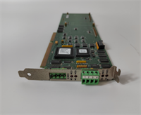
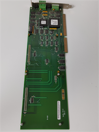
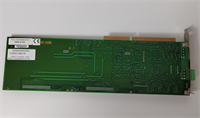
The IC660ELB921M is an electronic component designed for the GE Genius I/O system. It serves as the brain of the I/O module, handling the electronic processing and signal conditioning for the field inputs and outputs. This component bridges the gap between the physical sensors/actuators and the terminal block, ensuring accurate and reliable data transmission to the CPU.Engineered for robust industrial environments, the IC660ELB921M is built to withstand typical industrial conditions such as humidity, shock, and vibration. It features a durable design and is compatible with specific terminal blocks (IC660TBD025) to ensure seamless system integration. The electronic component handles the internal circuitry required to interpret and drive the signals.

Installation & Configuration Guide
Phase 1: Preparation (10 min)
- Safety First: Disconnect all power to the control panel. Follow Lockout/Tagout (LOTO) procedures to prevent accidental startup.
- Verify Compatibility: Confirm that the IC660ELB921M is compatible with your existing terminal blocks (IC660TBD025) and chassis.
- Gather Tools: You will need a Phillips screwdriver and possibly a multimeter to verify voltage levels.
Phase 2: Removal (5–10 min)
- Mark Wires: Before disconnecting anything, label all field wires connected to the terminal block for easy reconnection.
- Disconnect Power: Unplug the 24V DC power supply cable from the terminal block.
- Remove Screws: Loosen and remove the screws securing the electronic component to the terminal block.
- Extract: Carefully pull the electronic component away from the terminal block.
Phase 3: Installation (10 min)
- Mounting: Align the IC660ELB921M with the terminal block connector. Slide it into place until it clicks or secure it with screws.
- Reconnect Power: Plug the 24V DC power supply back into the terminal block.
- Wire Reconnection: Connect the field wires to the appropriate terminals. Ensure wires are securely fastened under the screw heads.
- Check Configuration: Verify that the voltage select jumpers (if present) are set to the correct position for your application (24VDC).
Phase 4: Power-On & Test (10 min)
- Visual Inspection: Look for any loose wires or obvious damage.
- Power Up: Restore power to the control panel.
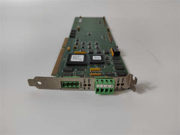
- LED Check: Observe the status LEDs on the electronic component and connected I/O modules. A steady green LED typically indicates normal operation.
- Function Test: Cycle the inputs and outputs to verify that signals are being processed correctly through the electronic component.
Troubleshooting Quick Reference
表格
| Symptom | Probable Cause | Corrective Action |
|---|---|---|
| No Power to Module | Loose Power Connection | Reconnect and tighten the 24V DC power cable. |
| Intermittent Signal Loss | Loose Field Wiring | Inspect and retighten all terminal screws on the terminal block. |
| Output Fault | Overcurrent Condition | Check the total load on the 16A output. Reduce the number of active outputs if necessary. |
| Input Noise | Electrical Interference | Ensure proper grounding and shielded cables are used for field wiring. |
| Communication Error | Improper Configuration | Verify the voltage select jumpers and ensure the electronic component is properly seated. |
Dimensions, Mounting & Wiring Notes
- Dimensions: 8.8 inches (W) x 3.5 inches (H) x 4.4 inches (D) (224mm × 90mm × 112mm).
- Mounting: The IC660ELB921M is designed for DIN rail mounting (35mm rail) or panel mounting using the provided hardware.
- Wiring: The electronic component uses screw-type terminals for field wiring. It supports 32 circuits (16 inputs and 16 outputs). Ensure you follow the wiring diagram in the user manual to avoid miswiring.
IC660ELB921M GE
FAQ
What is the difference between IC660ELB921M and IC660ELB921?
The “M” suffix typically denotes a specific revision or variant of the electronic component. It is crucial to verify that the physical dimensions and connector pinouts match your existing setup. Always cross-reference with the hardware manual to ensure full compatibility.Can I use this with a VersaMax CPU?
No. The IC660ELB921M is specifically designed for the GE Genius I/O system. It is not compatible with the VersaMax platform. You must use the appropriate electronic components designed for the VersaMax system (e.g., IC698ELB021).What voltage should I set the electronic component to?
The IC660ELB921M is designed to operate at 24V DC. The specific voltage depends on your system requirements. You must configure the internal jumpers or switches to match the voltage of your I/O modules and power supply.Is this a new or used part?
This is typically listed as “New Surplus” or “Refurbished.” New surplus parts are unused units from the original manufacturer’s inventory, while refurbished parts have been tested and verified to function correctly.What is the purpose of the “ELB” in the model number?
In GE Fanuc terminology, “ELB” typically stands for “Electronic Component” or “Electronic Block.” It identifies the part as the internal circuit board responsible for signal processing in the automation system.
GE IC660ELB921M Electronic Component