 Tel:
Tel:  Email:
  WhatsApp:
 Description
Key Technical Specifications
| Parameter | Specification |
|---|---|
| Manufacturer | GE Fanuc (General Electric) |
| Product Series | 90-70 |
| Model Number | IC600CB527M |
| Input/Output Types | Digital, Analog, Switch |
| Core Features | High Reliability, Industrial Control |
| Application | Power, Chemical, Water Treatment, etc. |
| Product Status | Active / Supported |
Product Introduction
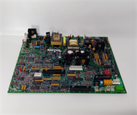
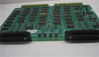
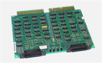
The IC600CB527M is an I/O control module manufactured by GE Fanuc for their 90-70 series PLC systems. It serves as the critical interface between the Programmable Logic Controller (PLC) and the physical industrial equipment in the field, such as sensors, actuators, and motors.This module converts real-world signals (like temperature, pressure, or switch states) into digital data that the PLC can process, and vice versa. It is a fundamental component in automating industrial processes, ensuring that the control system can reliably monitor and manage the production environment.
Installation & Configuration Guide
Phase 1: Preparation (10 min)
- Safety First: Disconnect all power to the control panel. Follow Lockout/Tagout (LOTO) procedures to prevent accidental startup.
- Verify Compatibility: Confirm that the IC600CB527M is compatible with your existing 90-70 PLC CPU and chassis.
- Gather Tools: You will need a Phillips screwdriver and a multimeter to verify voltage levels.
Phase 2: Removal (5–10 min)
- Mark Wires: Before disconnecting anything, label all field wires connected to the module for easy reconnection.
- Disconnect Power: Unplug the power supply cable from the module.
- Remove Screws: Loosen and remove the screws securing the module to the DIN rail or mounting panel.
- Extract: Carefully pull the module away from the mounting surface.
Phase 3: Installation (10 min)
- Mounting: Align the IC600CB527M with the DIN rail or panel mounting holes. Slide it into place until it clicks or secure it with screws.
- Reconnect Power: Plug the power supply back into the module.
- Wire Reconnection: Connect the field wires to the appropriate terminals. Ensure wires are securely fastened under the screw heads.
- Check Configuration: Verify any configuration switches or jumpers are set according to the system requirements for the specific I/O type being used.
Phase 4: Power-On & Test (10 min)
- Visual Inspection: Look for any loose wires or obvious damage.
- Power Up: Restore power to the control panel.
- LED Check: Observe the status LEDs on the module and the CPU. A steady green LED on the module typically indicates normal operation.
- Function Test: Cycle the inputs and outputs to verify that signals are being processed correctly through the module.
Troubleshooting Quick Reference
| Symptom | Probable Cause | Corrective Action |
|---|---|---|
| No Power to Module | Loose Power Connection | Reconnect and tighten the power cable. |
| Intermittent Signal Loss | Loose Field Wiring | Inspect and retighten all terminal screws. |
| Communication Error | Improper Configuration | Verify the module is properly seated and configuration settings are correct. |
| Output Fault | Overcurrent Condition | Check the total load on the module. Reduce the number of active outputs if necessary. |
| Input Noise | Electrical Interference | Ensure proper grounding and shielded cables are used for field wiring. |
Dimensions, Mounting & Wiring Notes
- Dimensions: Specific dimensions are not listed in the available documentation.
- Mounting: The IC600CB527M is designed for DIN rail mounting (35mm rail) or panel mounting using the provided hardware.
- Wiring: The module handles various signal types (digital, analog, switch). It is crucial to follow the wiring diagram in the user manual to avoid miswiring and ensure proper signal conversion.
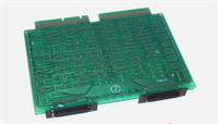
IC600CB527M GE
FAQ
What is the difference between IC600CB527M and IC600CB527?
The model numbers appear identical. It is possible that “IC600CB527M” is a specific revision or variant of the standard “IC600CB527” module. You must verify the physical dimensions, connector pinouts, and firmware compatibility with your existing system.Can I use this with a VersaMax CPU?
No. The IC600CB527M is specifically designed for the GE 90-70 series PLC. It is not compatible with the VersaMax platform. You must use the appropriate I/O modules designed for the VersaMax system (e.g., IC698CB527).What type of signals does this module handle?
The IC600CB527M is a versatile I/O control module that supports multiple signal types, including digital (on/off), analog (continuous range like 4-20mA), and switch inputs. The specific configuration depends on the physical I/O blocks installed in the module.Is this a new or used part?
This is typically listed as “New Surplus” or “Refurbished.” New surplus parts are unused units from the original manufacturer’s inventory, while refurbished parts have been tested and verified to function correctly.What is the purpose of this module?
The IC600CB527M acts as the bridge between the PLC and the industrial field. It receives signals from sensors and sends control commands to actuators, enabling the automation system to monitor and manage the physical process.
GE IC600CB527M I/O Control Module