
 Tel:
Tel:  Email:
  WhatsApp:
 Description
Key Technical Specifications
| Parameter | Specification |
|---|---|
| Part Number | F650-G-N-A-B-F-2-G-1-HI-C-E |
| Protection Type | Feeder / Generator / Motor |
| Diff. Protection | HI (High Impedance Differential) |
| Communication | Ethernet (IEC 61850, Modbus TCP) + Serial |
| Digital Inputs | 16 Isolated Inputs (Typical for ‘B’ config) |
| Outputs | 8 Output Relays (Typical for ‘F’ config) |
| Analog Inputs | 4 Current (CT), 4 Voltage (VT) |
| Power Supply | Universal (110-250 VDC / 120-230 VAC) |
| Metering | True RMS (V, I, Hz, W, VA, PF) |
| Environment | -40°C to +70°C (Wide Temp Range) |
Product Introduction
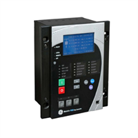
In the field, we don’t just need a relay that trips; we need one that talks to us when things go wrong. The GE F650-G-N-A-B-F-2-G-1-HI-C-E is a beast from the Multilin family, specifically designed for feeder management but robust enough for generator step-up applications.The “HI” in the model number is the key differentiator here. This unit supports High Impedance Differential Protection. If you are protecting a transformer or a busbar, this is non-negotiable. It prevents false tripping during external faults where CT saturation might fool a standard low-impedance relay. It’s got a high-resolution oscillography recorder (up to 5 seconds at max sample rate), which is a lifesaver when you’re trying to figure out why a breaker popped three days ago. It handles the “dirty” power environment—voltage sags, harmonics, and CT failures—without blinking.
Quality SOP & Tech Pitfalls (The Reality Check)
The Lab Report (SOP)
When I bench-test an F650, I don’t just check if it powers up. Here is the protocol:
- Visual Inspection: Check the rear terminal block pins. These units are heavy, and shipping can bend the backplane connectors.
- Power Up: Apply auxiliary voltage (e.g., 125V DC). Verify the “Healthy” LED illuminates.
- Display Test: Check the front LCD. Dead pixels are common on older stock; ensure you can read the menu.
- Injection Test: Inject 1A secondary current. Verify the display reads 1.00A ±0.5%.
- Trip Test: Inject a fault current (>pickup setting). Watch the output relay click and verify the target LED latches.
- Comms Check: Ping the IP address via Ethernet. Try connecting with EnerVista software.
The Engineer’s Warning (Pitfalls)
The biggest headache with the F650 series is CT Circuit Integrity.This relay has sophisticated logic to detect “CT Trouble” (open circuits). If your wiring is loose or your shorting blocks aren’t fully engaged, the relay will see zero sequence current and block the differential element to prevent a nuisance trip. It’s doing its job, but it leaves your asset unprotected. Always megger your CT wiring before connecting it to the relay. Also, watch the Harmonic Restraint settings. If you are feeding a large transformer, inrush current can look like a fault. Ensure the 2nd harmonic blocking is enabled, or you’ll trip on startup.
Installation & Configuration Guide
Swapping this relay requires care with the CT circuits. An open CT secondary can generate lethal voltages.
- Pre-Installation ⚠️
- Safety: Lockout/Tagout the CT and VT circuits. Short the CT secondaries immediately.
- Documentation: Photograph the rear wiring. The terminal numbering is small and easy to miss.
- Removal
- Disconnect the communication cables (Ethernet/Serial) first.
- Remove the terminal block screws. Pull the connector block straight out.
- Unbolt the unit from the panel (usually 4 M6 bolts).
- Installation
- Mount the new F650. Ensure it is grounded properly to the panel copper.
- Insert the terminal blocks. Torque the screws. Loose connections cause heat and resistance errors.
- Reconnect comms cables.
- Power-On & Testing
- Remove CT shorts only after wiring is verified.
- Apply auxiliary power.
- Settings Upload: Connect via USB/Ethernet. Upload your
.f65settings file. Do not rely on manual entry; it’s too error-prone. - Verify “Ready” status.
F650-G-N-A-B-F-2-G-1-HI-C-E GE
Compatible Replacement Models
The F650 has evolved, but the core functionality remains similar across revisions.
- ✅ Drop-in Replacement: F650-G-N-A-B-F-2-G-1-HI-C-E. Exact match.
- ⚠️ Functional Equivalent: F650B. The “B” revision often implies updated processor speed or memory, but physically fits the same slot. Requires checking firmware compatibility.
- ❌ Different Protection: F650-LI. The “LI” stands for Low Impedance. Do not swap an HI (High Impedance) unit for an LI unit without re-evaluating your protection scheme. They handle CT saturation differently.
Frequently Asked Questions (FAQ)
What does the “HI” suffix mean?
It stands for High Impedance Differential Protection. This is a specific type of protection used for busbars and transformers to remain stable during external faults. If your system was designed for High-Z protection, you cannot use a standard Low-Z relay.Can I hot-swap this relay?
No. Unlike some modern PLCs, removing this relay while the breaker is live removes the protection layer. Furthermore, disconnecting the CT wires while current is flowing creates dangerous arcing voltages. Always de-energize and short the CTs first.Why is the “CT Trouble” LED lit?
This usually means an open circuit in your CT wiring or a blown fuse in the voltage circuit. The relay detects an imbalance that suggests the measurement is invalid. Check your terminal block wiring and field cabling immediately.Does this support IEC 61850?
Yes, the “G” and “E” suffixes typically indicate the presence of Ethernet ports capable of running IEC 61850, DNP3, and Modbus TCP. This allows it to talk directly to SCADA systems without a gateway.How do I clear a latched trip?
You can reset targets locally using the front keypad (Reset button) or remotely via a digital input or communication command. However, you must clear the underlying fault condition (overcurrent) first, or it will just trip again.


