 Tel:
Tel:  Email:
  WhatsApp:
 Description
Key Technical Specifications
| Parameter | Specification |
|---|---|
| Product Type | Field Bus Management System Controller |
| Processor Architecture | 32-bit Industrial RISC |
| Program Memory | 8 MB |
| Data Memory | 4 MB |
| Execution Speed | 0.1 µs/Boolean, 0.5 µs/Float |
| Communication Ports | Dual 10/100Mbps Fiber Optic Ethernet |
| Fieldbus Support | Supports up to 32 FBM modules (expandable to 128) |
| Power Input | 24 VDC (Redundant capable) |
| Power Consumption | Approx. 10W |
| Mounting Type | Panel/Chassis Mount (DIN Rail compatible) |
| Dimensions | 140mm x 165mm x 45mm |
| Operating Temp | 0°C to +60°C |
Product Introduction
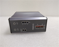
The Foxboro FBMSVH is a high-performance Field Bus Management System Controller that acts as the central processing unit for industrial automation nodes. It manages complex logic execution and data acquisition, bridging the gap between field devices (like sensors and valves) and the plant network. This module is critical for maintaining control continuity in the I/A Series architecture.Unlike standard PLCs, the FBMSVH features a redundant architecture design, allowing for seamless failover if paired with a backup unit. With 8MB of memory and a fast RISC processor, it handles heavy mathematical calculations and loop tuning without bogging down the scan time. The inclusion of fiber optic Ethernet ports makes it immune to electrical noise, which is a common headache in steel mills or power plants.
Installation & Configuration Guide
Phase 1: Preparation (10 min)
- Power Isolation: Turn off the 24VDC supply. Verify zero voltage at the input terminals.
- ESD Precautions: Strap on your anti-static wristband. The processor traces are delicate.
- Inspect Slot: Ensure the mounting surface or carrier slot is clean. Dust can interfere with the backplane connection.
Phase 2: Removal (Old Unit Only)
- Label Cables: Mark the fiber optic cables (Port A/B) and power wires. Fiber connectors are keyed, but labeling prevents “oops” moments.
- Unlock: Release the retention clips or unscrew the faceplate screws.
- Extract: Slide the FBMSVH out gently. Do not pull on the cables; pull from the module body.
Phase 3: Installation (New Unit)
- Align: Position the FBMSVH into the designated slot or DIN rail.
- Seat: Push firmly until the rear connector engages. You should feel a solid stop.
- Secure: Lock the retention mechanism. Tighten screws to approx. 5 in-lbs (snug, don’t strip).
- Connect: Plug in the fiber optic cables. Listen for the “click.” Reconnect the 24VDC power wiring.
Phase 4: Power-On & Test
- Energize: Apply 24VDC power.
- LED Status:
- RUN: Solid green indicates the OS has loaded.
- COMMS: Blinking green shows network traffic.
- FAULT: Must be off. If red, check the DIP switches or firmware version.
- Handshake: Connect via the engineering port (Ethernet/Serial). Verify the node address matches your system configuration.
Troubleshooting Quick Reference
| Symptom | Probable Cause | Corrective Action |
|---|---|---|
| No LEDs lit | Power supply failure | Check 24VDC input voltage. Verify polarity on the terminal block. |
| FAULT LED Red | Firmware mismatch or corruption | Verify the firmware version (e.g., v2.x vs v3.x) matches the rest of the system. Reload if needed. |
| Fiber Link Down | Cable break or dirty connector | Inspect fiber tips for dust/dirt. Clean with alcohol wipes. Check for sharp bends in the cable. |
| System Not Detected | Node address conflict | Check the rotary switches (if present) or software assignment for duplicate node IDs. |
| Intermittent Comm | Ground loop or noise | Ensure the chassis is properly grounded. Fiber optics usually solve this, but check the power ground. |
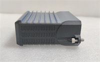
Dimensions, Mounting & Wiring Notes
- Form Factor: Compact rectangular module.
- Size: 140mm (H) x 165mm (W) x 45mm (D).
- Mounting: Designed for panel mounting or specific I/A Series carriers. Can be DIN-rail mounted with appropriate adapter.
- Connections:
- Network: LC or ST style Fiber Optic connectors (check specific revision).
- Power: Removable terminal block (24VDC).
- Service: RJ-45 or DB9 for local service connection.
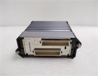
FBMSVH FOXBORO
FAQ
1. What is the difference between FBMSVH and an FBM?
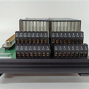
An FBM (Field Bus Module) is typically an I/O card (handling analog/digital signals). The FBMSVH is the controller—it’s the brain that tells the FBMs what to do. You usually have one FBMSVH managing several FBMs.2. Can I hot-swap this controller?
If your system is configured for redundancy (two FBMSVH units running in parallel), yes. You can pull the faulty one, and the backup will take over. Swapping a single, non-redundant controller will stop the process.3. Why use Fiber Optic instead of Copper Ethernet?
Fiber provides total electrical isolation. In environments with high voltage spikes (like welding shops or near large motors), copper ethernet can fry the controller. Fiber is immune to EMI/RFI interference.4. My FAULT light is flashing amber. What does that mean?
Amber usually indicates a “Minor Fault” or “Out of Service” status. It might be waiting for a download from the workstation, or a connected I/O module is missing. Check the diagnostic logs in your software.5. Does this replace older models like the P0916PZ?
The FBMSVH is often a successor or upgrade path for older I/A Series processors, but you must verify compatibility with your existing chassis and software version before swapping.