 Tel:
Tel:  Email:
  WhatsApp:
 Description
Key Technical Specifications
| Parameter | Specification |
|---|---|
| Data Rate | 10/100 Mbps (Auto-sensing) |
| Protocol | Modbus TCP/IP, Ethernet/IP |
| Processor | 32-bit RISC Industrial Processor |
| Memory | 8 MB Program / 4 MB Data |
| Power Supply | 24V DC (Redundant input capable) |
| Power Consumption | ≤5W (Internal) |
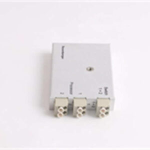
| Connection | RJ45 (Copper) or Fiber Optic (depending on sub-type) |
| Operating Temp | 0°C to 60°C (32°F to 140°F) |
| Dimensions | 140mm x 165mm x 45mm |
| Weight | Approx. 0.6 kg |
Product Introduction
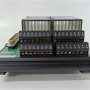
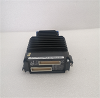
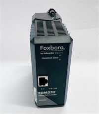
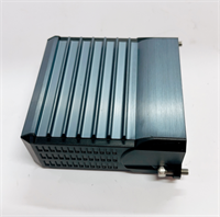
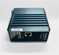
The Foxboro FBM232 P0926GW is a dedicated communication module within the I/A Series Distributed Control System (DCS). It acts as a bridge, connecting third-party intelligent field devices—such as analyzers, PLCs, or smart sensors—to the main control network. By supporting standard Ethernet protocols like Modbus TCP, it allows engineers to integrate diverse hardware without complex gateway wiring.This module distinguishes itself through its processing capability and redundancy features. It contains an onboard 32-bit RISC processor that handles protocol conversion locally, offloading the main system controller. With a data transfer rate of up to 100 Mbps, it ensures real-time synchronization of critical process variables. The unit is housed in a rugged cast aluminum enclosure rated IP20, making it suitable for harsh industrial environments where dust and electromagnetic interference are concerns.
Installation & Configuration Guide
Phase 1: Preparation (10 min)
- System Check: Ensure the FCP (Field Control Processor) is powered down or the specific slot is disabled in the software to prevent bus conflicts.
- ESD Safety: Attach an anti-static wrist strap to the cabinet ground.
- Hardware Inspection: Verify the P0926GW label matches your order. Check the RJ45 port pins for straightness (a common damage point).
Phase 2: Removal of Old Unit (If applicable) (5–10 min)
- Label Cables: If connected, tag Ethernet cables “Port A” or “Port B” to maintain network topology.
- Disconnect: Unplug the Ethernet cable and the 24V DC power connector.
- Unlatch: Release the mounting clips or screws securing the module to the DIN rail or chassis.
- Extract: Slide the module out carefully.
Phase 3: Installation (10 min)
- Mounting: Slide the FBM232 P0926GW onto the DIN rail or into the chassis slot.
- Secure: Engage the locking mechanism. It should feel rigid with no wobble.
- Power Wiring: Connect the 24V DC supply. If using redundant power, wire both inputs.
- Network: Plug the Ethernet cable into the RJ45 port. Ensure the clip clicks.
Phase 4: Power-On & Test (10 min)
- Energize: Apply 24V DC power.
- LED Status: Look for the “PWR” LED to turn solid green. The “LINK” LED on the Ethernet port should blink or stay solid, indicating physical layer connectivity.
- Software Handshake: Open the engineering workstation (e.g., Foxboro Evo or InTouch). Navigate to the Device Management tree.
- Verify: Confirm the module reports “Online” and the firmware version matches the system requirements.
Troubleshooting Quick Reference
| Symptom | Probable Cause | Corrective Action |
|---|---|---|
| No Power LED | Loose 24V connection or blown fuse | Check terminal block tightness. Measure input voltage (should be 24V ±10%). |
| Link LED Off | Cable fault or switch port mismatch | Replace Cat5/Cat6 cable. Verify the switch is set to 10/100 Auto-negotiate. |
| Comms Timeout | IP Address conflict or wrong Subnet | Check DIP switches or software config for correct IP. Ping the module from a laptop. |
| Data Garbage | Endianness or Protocol mismatch | Verify Modbus register mapping (Big vs. Little Endian) in the driver configuration. |
Dimensions, Mounting & Wiring Notes
- Dimensions: 140mm (H) x 165mm (W) x 45mm (D).
- Mounting: Standard DIN Rail or I/A Series specific carrier.
- Wiring Note: Use shielded twisted pair (STP) for Ethernet connections in high-noise areas. Keep the 24V DC power lines separate from signal cables to prevent noise injection.
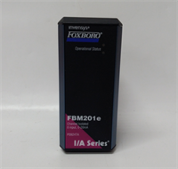
FBM232 P0926GW FOXBORO
FAQ
What is the difference between FBM232 and FBM233?
The FBM232 (P0926GW) typically supports standard Ethernet communication. The FBM233 (P0926GX) often adds support for fiber optic interfaces or specific redundancy features. Always check the datasheet for the exact port types required by your plant design.Can I use this module for Modbus RTU?
Primarily, this module is designed for Ethernet-based protocols (Modbus TCP). If you need serial Modbus RTU, you usually look at the FBM2xx series specifically designated for serial interfaces, though some configurations allow tunneling.I replaced the card, but the system says “Configuration Mismatch.” What do I do?
This usually means the firmware version on the new card doesn’t match the system database. You may need to perform a firmware download from the engineering station or replace the card with one of the exact revision level.Does this support redundant power?
Yes, the module architecture supports redundant 24V DC inputs. This ensures that if one power supply leg fails, the communication link remains active.Is the P0926GW compatible with the Foxboro Evo system?
Yes, it is fully compatible and commonly used to integrate legacy devices or third-party equipment into the modern Foxboro Evo control environment.