
 Tel:
Tel:  Email:
  WhatsApp:
 Description
Key Technical Specifications
| Parameter | Specification |
|---|---|
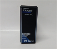
| Part Number | P0926GG |
| Module Type | Modbus Communication Interface |
| Communication Ports | 4 x Isolated Serial Ports (via Terminal Assembly) |
| Protocols | Modbus RTU (Master/Slave) |
| Interface Standards | Software selectable: RS-232, RS-422, or RS-485 |
| Device Capacity | Up to 64 Modbus slave devices per module |
| Transactions | Up to 64 independent transactions per device |
| Power Input | 24V DC (Nominal), Range: 19–36V DC |
| Power Consumption | Approx. 10W |
| Operating Temp | 0°C to 60°C |
| Enclosure Rating | IP20 (Cast Aluminum Housing) |
| Dimensions | 140mm x 165mm x 45mm |
Product Introduction
If you’ve ever tried to get a modern PLC to talk to an ancient flow meter or a third-party analyzer, you know the headache of serial communication. The Foxboro FBM224 (P0926GG) is the industrial diplomat designed to solve exactly that problem. It’s a dedicated Modbus communication module for the I/A Series system. Instead of forcing your main processor to waste cycles polling serial devices, you offload that work to this card.This isn’t just a simple converter; it’s a robust interface that handles the heavy lifting. It supports four independent channels, meaning you can daisy-chain multiple devices on different protocols (one port RS-485, another RS-232, etc.) simultaneously. I’ve seen these modules sitting in cabinets for 15 years, happily polling gas detectors without a single hiccup. However, the configuration can be finicky if you don’t understand how Modbus addressing works. It takes the data from those “dumb” serial devices and maps it directly into the Foxboro control database, making it look like native I/O.
Quality SOP & Tech Pitfalls (The Reality Check)
The Lab Report (SOP)
We don’t trust “pulls” from the field. Here is how we verify a P0926GG before it goes in the box:
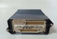
- Visual Inspection: We check the terminal assembly connectors (the black blocks on the side). These are notorious for cracking if someone overtightened the screws. We also inspect the PCB for corrosion near the heat sinks.
- Port Loopback Test: This is critical. We connect a loopback plug to each of the 4 ports and send data. If Port 1 sends but doesn’t receive, the driver chip is fried. All 4 ports must pass TX/RX verification.
- Modbus Stress Test: We hook the module up to a test rack with a simulated Modbus slave. We force the module to read registers at high speed to ensure the buffer doesn’t overflow.
- Firmware Verification: We check the internal revision. Older firmware versions had issues with specific baud rates (like 19200 or 38400).
The Engineer’s Warning (Pitfalls)
- The DIP Switch Nightmare: The FBM224 uses a massive bank of DIP switches to configure the serial parameters (baud rate, parity, stop bits). I have seen technicians spend days troubleshooting a “bad card” only to find out they missed one tiny switch setting. Photograph the switches on the old card before you pull it.
- Terminal Assembly (TA) Confusion: This module requires a specific Terminal Assembly (TA) to break out the DB-25 style connections to screw terminals. If you buy the module but don’t have the matching TA, or if the wiring on the TA is wrong, the module will sit there blinking a fault code.
- Field Disaster: A plant manager once replaced a failed FBM224 but didn’t realize the old one had a specific “broadcast disable” jumper set. The new card allowed broadcast writes, which accidentally reset the setpoints on 20 temperature controllers downstream. Always verify the transaction table logic.
Installation & Configuration Guide
Swapping this card is easy; configuring it is where the job is.
- Pre-Installation Safety
- ⚠️ CRITICAL: Identify the cabling. The FBM224 connects via a complex cable harness to the Terminal Assembly. Label every connector (J1, J2, etc.) before unplugging.
- Take a high-resolution photo of the DIP switch banks on the front of the old module. Compare them against the system documentation.
- Removal
- Disconnect the communication cables carefully.
- Release the top and bottom locking tabs.
- Slide the module out. Note that the connectors are tight; do not wiggle it excessively or you might damage the backplane pins.
- Hardware Setup
- Place the new P0926GG on an anti-static mat.
- Set the Switches: Manually toggle the DIP switches on the new module to match your photos exactly. Pay special attention to the termination resistor switches (usually the last few switches)—these must match the physical network layout.
- Insert the module into the I/O carrier slot. Ensure it seats flush. Lock the latches.
- Power-Up & Commissioning
- Apply power. The LED should cycle through a self-test (Red -> Green blink).
- Connect your engineering workstation.
- Use the Configurator Tool (Windows/Solaris based) to verify the “Device Transaction” file. If the software says “Comm Fail,” check your baud rate settings first. That is the culprit 9 times out of 10.
FBM224 P0926GG FOXBORO
Compatible Replacement Models
- ✅ Drop-in Replacement: FBM224 (P0926GG). Any revision of this part number is generally hardware compatible, provided you update the firmware.
- ⚠️ Functional Alternative: FBM223. This is the Profibus version. Do not use this unless you are migrating your entire network from Modbus to Profibus.
- ❌ System Upgrade: Foxboro Evo Controller with Integrated Serial. Moving to the newer Evo platform often integrates these comms into the controller, rendering the separate FBM224 obsolete.
Frequently Asked Questions (FAQ)
Q: Can I mix RS-232 and RS-485 devices on the same FBM224?
A: Yes. Each of the four ports is independently configurable. You can have Port 1 talking to an RS-232 printer and Port 2 talking to an RS-485 drive, provided the Terminal Assembly is wired correctly for both standards.Q: My LED is flashing “Code 4”. What does that mean?
A: Flash codes vary by firmware, but Code 4 usually indicates a configuration error or a failure to initialize the communication buffers. Check your DIP switch settings against the software config. They must match perfectly.Q: Does this module support Modbus TCP/IP?
A: No. The FBM224 is strictly for serial Modbus (RTU/ASCII). If you need Ethernet-based Modbus (TCP), you are looking for a different type of interface or a gateway.Q: How many devices can I actually hang on one port?
A: Theoretically, the module supports 64 devices total. However, electrically, RS-485 is limited to 32 loads (unless you use repeaters). Don’t try to daisy-chain 64 drives on one port without checking the impedance calculations.Q: Is the P0926GG redundant?
A: The module itself is not internally redundant. However, you can install two FBM224s in a redundant pair configuration in the I/A Series carrier, so if one fails, the other takes over the polling duties.