 Tel:
Tel:  Email:
  WhatsApp:
 Description
⚙️ Key Technical Specifications
| Parameter | Specification |
|---|---|
| Part Number | P0916WV (Verify specific revision) |
| Input Channels | 4 (Universal Analog) |
| Signal Types | TC (J, K, T, E, R, S, B), RTD (Pt100, Cu10), 0-20mA, 0-10V |
| Conversion Method | Sigma-Delta Modulation |
| Accuracy | ±0.1% of Span (Typical) |
| Isolation | 600 VAC (Channel-to-Channel & Channel-to-Bus) |
| Update Rate | User selectable (e.g., 250ms, 500ms, 1s) |
| Cold Junction Comp | Internal automatic compensation for Thermocouples |
| Power Dissipation | ~3.5 Watts (varies by load) |
| Operating Temp | -20°C to +70°C (-4°F to +158°F) |
📝 Product Introduction
In the world of process control, “universal” usually means “complicated,” but the Foxboro FBM201E manages to be versatile without being a headache. This is your go-to module when you have a messy mix of sensors—maybe a Type K thermocouple on one loop, a Pt100 RTD on another, and a standard 4-20mA pressure transmitter on the third. Instead of stocking three different cards, you stock this one.I’ve deployed these in packaging lines where space was tight and sensor types varied wildly. The standout feature here is the channel-to-channel isolation. On cheaper modules, if one channel gets hit with a voltage spike (say, from a nearby motor starter), the whole card glitches out. With the FBM201E, that noise stays trapped on Channel 1; Channels 2, 3, and 4 keep humming along perfectly. It’s accurate (16-bit resolution is plenty for most industrial processes) and handles the harsh electrical environment of a factory floor much better than the older 100-series cards.
🛡️ Quality SOP & Tech Pitfalls (The Reality Check)
The Lab Report (SOP)
We don’t just ship boxes; we verify the signal path. Here is our pre-shipment protocol:
- Visual Inspection: We inspect the PCB for corrosion or burnt traces, specifically around the input terminals. We check the date code; old stock needs verification.
- Precision Injection: We use a Fluke 744 or similar precision calibrator to inject a simulated Type K Thermocouple signal (e.g., 400°C) and a 12mA current signal simultaneously.
- Drift Check: We monitor the values for 15 minutes. If the reading drifts more than 0.05%, the ADC reference is likely failing.
- Isolation Test: We verify the optical isolation barriers are intact using a megohmmeter (at safe low voltage levels) between the input terminals and the backplane connector.
The Engineer’s Warning (Pitfalls)
⚠️ Field Disaster Story:
A plant manager once called me in a panic because his reactor temperatures were reading “off the scale high” immediately after a maintenance shutdown. He had swapped the FBM201E but reused the old wiring block.The Fix: He had wired a 24V DC discrete signal into Channel 3, thinking it was a digital input card. Because he didn’t check the Terminal Assembly (TA) wiring diagram, he fried the input protection on that channel. The FBM201E is an Analog input. Do not put discrete 24V switching signals on it unless they are strictly 0-10V analog references. Also, always check the Cold Junction Compensation (CJC) setting if your TC readings seem offset by exactly the ambient room temperature.
🔧 Installation & Configuration Guide
Time estimate: 30 minutes.
- Pre-Installation Safety
- ⚠️ CRITICAL: Remove field power. Short-circuit any thermocouple inputs if possible to prevent noise pickup during install.
- Identify your sensor type (TC vs RTD). RTDs often require 3-wire or 4-wire connections for accuracy; ensure your field wiring matches the Terminal Assembly schematic.
- Removal
- Label the field wiring at the terminal block.
- Unscrew the terminal block (if removable) or disconnect wires.
- Release the module locking mechanism and slide the FBM201E out of the carrier.
- Installation
- Check Jumpers/DIPs: Some revisions allow you to select filter frequencies (50Hz vs 60Hz) via hardware jumpers. Ensure this matches your local grid frequency to reject noise.
- Slide the new module into the slot. Push firmly until the backplane connector seats.
- Tighten the retention screws. Re-connect field wiring. Tighten terminals securely—loose thermocouple wires cause erratic temperature swings.
- Power-On & Testing
- Restore power. Watch the LED status.
- Solid Green: Module is healthy and communicating.
- Amber/Flashing: Configuration mismatch or channel error.
- Go to the workstation. Verify the “Raw Value” matches your injected signal. If using RTDs, check that the “3-wire compensation” is enabled in software if applicable.
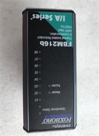
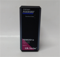
FBM201E FOXBORO
🔄 Compatible Replacement Models
| Model | Compatibility Tier | Notes |
|---|---|---|
| FBM201E | ✅ Drop-in Replacement | Exact match. Preferred revision for new installs. |
| FBM201 P0914SQ | ⚠️ Software Compatible | Older revision. Pinout is compatible, but firmware handling may differ slightly. |
| FBM203 P0914TR | ❌ Hardware Mod Required | Different function (Discrete Input). Not compatible. |
❓ Frequently Asked Questions (FAQ)
Can I use this module for 4-20mA transmitters?
Yes. The FBM201E is a “universal” input. You can configure any of the 4 channels to accept 0-20mA or 4-20mA signals. Just remember: this module provides voltage or current input sensing. If your transmitter requires loop power, ensure your system design includes an internal power option or an external 24V supply.What is the difference between FBM201 and FBM201E?
The “E” revision generally offers improved noise immunity, faster update rates, and better compatibility with newer versions of the I/A Series software (Control Core Services). If you are mixing them in the same rack, check the compatibility matrix, but generally, the “E” is the superior, backward-compatible evolution.Why are my thermocouple readings fluctuating?
If the readings jump around, check two things:
- Grounding: Ensure your thermocouple probe isn’t grounded in a way that creates a ground loop, although the FBM201E has good isolation.
- Breakage: A broken wire in a TC circuit often reads “High Scale” (max temp). A loose connection causes random spikes.
Does this support RTDs?
Yes, it supports 2-wire, 3-wire, and 4-wire RTDs (typically Platinum 100Ω or Copper 10Ω). For the best accuracy, always use the 3-wire configuration if your sensor supports it, as this allows the module to compensate for lead wire resistance.Do I need a special terminal block?
Yes. The FBM201E mates with specific 200 Series Terminal Assemblies (TAs) like the NCM or specific screw-terminal blocks designed for the 200 series. Ensure the TA matches the pinout of the FBM201E, as some older 100-series TAs are physically similar but electrically different.