
 Tel:
Tel:  Email:
  WhatsApp:
 Description
Key Technical Specifications
| Parameter | Specification |
|---|---|
| Manufacturer | Foxboro (Schneider Electric) |
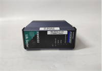
| Part Number | P0973CA |
| Model ID | FEM100 |
| Function | Fieldbus Expansion Module |
| Communication Speed | 2 Mbps |
| Supply Voltage | 12.5 – 42 VDC |
| Operating Temp | 0°C to 60°C |
| Data Capacity | 16 MB (System dependent) |
| Certification | UL Listed |
| Origin | USA |
Product Introduction
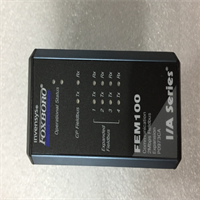
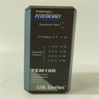
The Foxboro FEM100 P0973CA is a Fieldbus Expansion Module designed for the I/A Series control system. It acts as a communication bridge, handling data transmission between field devices and the central controller at speeds up to 2 Mbps. This unit is essential for expanding network capacity or replacing failed communication interfaces in legacy automation setups.Engineered for stability in harsh environments, the module operates reliably within a 0°C to 60°C range. It supports redundancy configurations, ensuring continuous operation even if a primary path fails. The unit accepts a wide input voltage range (12.5–42VDC), making it adaptable to various power supply conditions found in older plant infrastructures.
Installation & Configuration Guide
Phase 1: Preparation (10 min)
- Gather tools: Anti-static wrist strap, flathead screwdriver, multimeter.
- Verify the replacement FEM100 P0973CA matches the label of the faulty unit.
- Check the backplane slot for debris or bent pins.
Phase 2: Removal (5–10 min)
Warning: Do not hot-swap this module unless the specific chassis configuration explicitly supports live removal. Power down if unsure.
- Disconnect field wiring from the terminal block.
- Unscrew the locking mechanism securing the card to the rack.
- Gently pull the module straight out. If resistance is high, check for hidden screws.
Phase 3: Installation (10 min)
- Align the P0973CA guide rails with the chassis slots.
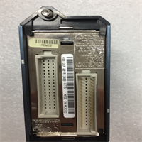
- Insert the module firmly until the backplane connector seats fully.
- Secure the locking screws to ensure proper grounding contact.
- Reconnect wiring according to the termination diagram (check polarity).
Phase 4: Power-On & Test (10 min)
- Apply 24VDC power (nominal). Measure voltage at the terminals; it should be within ±10%.
- Observe the LED indicators. A steady green “Comm” light usually indicates a healthy handshake.
- Verify communication status via the system workstation (AW).
Troubleshooting Quick Reference
| Symptom | Probable Cause | Corrective Action |
|---|---|---|
| No LEDs lit | Power loss or blown fuse | Check 12.5-42VDC input. Verify fuses on the carrier board. |
| Red Fault LED | Internal hardware failure | Reseat the card. If persistent, replace the module. |
| Comm Link Down | Cable break or termination | Inspect shield connections. Ensure terminators are set correctly. |
| Intermittent Data | Ground loops or noise | Verify single-point grounding. Check cable routing near VFDs. |
Dimensions, Mounting & Wiring Notes
- Form Factor: Standard I/A Series plug-in unit.
- Mounting: Horizontal insertion into the carrier/rack. Secured by captive screws.
- Connections: typically utilizes screw terminals or a pre-wired termination assembly (TA).
- Note: Ensure the DIN rail or mounting surface is clean to prevent vibration issues.

FEM100 P0973CA FOXBORO
FAQ
Can I use the P0973CA in a redundant setup?
Yes, the FEM100 architecture supports redundancy. However, you must configure the system software to recognize the backup path.Does this come with a warranty?
We provide a standard one-year warranty on all surplus tested modules.What does the “FEM” stand for?
It stands for Fieldbus Expansion Module. It expands the node bus capability.Is the price listed real?
Prices vary based on stock condition (New vs. Refurbished). Please request a formal quote for accuracy.I have an old I/A Series system, will this fit?
This is designed for the I/A Series. Verify your chassis type (e.g., Carrier Band) to ensure compatibility before purchasing.