 Tel:
Tel:  Email:
  WhatsApp:
 Description
Product Introduction
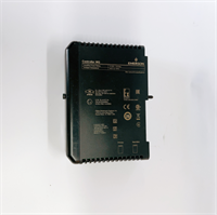
Let’s cut to the chase. The EMERSON ST341A-25-ASSY-EM is a complete assembly kit for the Fisher™ ST341 series smart positioner. It serves as the brain of the control valve, translating the 4-20 mA signal from your DCS into a precise 3-15 psi pneumatic output to move the valve stem exactly where it needs to go. This isn’t just a replacement part; it’s the core actuation logic for critical process loops.What sets this assembly apart is its robust design for harsh environments and its support for HART communication. In deployments across refineries, we found its diagnostic capabilities significantly cut down troubleshooting time. It handles the full 3-15 psi range with a solid 20-100 kPa pressure rating. If you’re looking to upgrade an old pneumatic positioner or replace a faulty unit in an EOL system, this ST341A kit is the drop-in solution that keeps the valve moving accurately.
Key Technical Specifications
| Parameter | Value |
|---|---|
| Model Number | ST341A-25-ASSY-EM |
| OEM Brand | EMERSON / FISHER |
| Product Type | Smart Valve Positioner Assembly |
| Input Signal | 4-20 mA DC + HART Protocol |
| Pneumatic Output | 3-15 psi (Standard Range) |
| Supply Pressure | 20-100 kPa (Min-Max) |
| Bench Range | 3-15 psi (Adjustable) |
| Communication | HART (Highway Addressable Remote Transducer) |
| Mounting Type | Direct Mount (Yoke) |
| Actuator Compatibility | 6″ & 10″ Diaphragm Actuators |
| Environment | Industrial / Hazardous Area (Verify Cert) |
Installation & Wiring Guide
Phase 1: Preparation (Est. 10 min)
- Safety First: Isolate the process fluid and vent all air pressure from the actuator. Don’t trust the gauge—vent manually.
- Toolkit: Gather a 3/4″ wrench, 5 mm Allen key, and a HART communicator (or DCS terminal).
- Document: Take a photo of the current linkage setup. Even if it looks simple, the lever arm position is critical.
Phase 2: Removal of Old Unit (Est. 15 min)
- Depressurize: Ensure zero air pressure in the tubing.
- Disconnect: Remove the air tube from the output port.
- Unlink: Loosen the clamps on the feedback lever and slide it off the pin.
- Unbolt: Remove the four mounting bolts securing the positioner to the yoke.
Phase 3: Installing the ST341A (Est. 20 min)
- Mount: Slide the new ST341A-25-ASSY-EM onto the yoke. Ensure the mounting surface is clean.
- Linkage: Reconnect the feedback lever. Crucial: Match the exact hole position on the lever as per your photo. A wrong hole changes the stroke calibration.
- Tubing: Reconnect the air supply and output tubing. Use Teflon tape on threads if required.
- Wiring: Connect the 4-20 mA wires to terminals 1 (+) and 2 (-). Polarity matters.
Phase 4: Calibration & Test (Est. 30 min)
- Power Up: Restore air supply (20 psi) and electrical power.
- Auto-Config: Use a HART communicator to trigger the “Auto Setup” or “Travel Calibration” function.
- Verify: Watch the output pressure gauge. It should sweep smoothly from 3 psi to 15 psi as the signal goes 4-20 mA.
- Leak Check: Spray soapy water on all fittings. Bubbles mean leaks—tighten until dry.