 Tel:
 Email:
 WhatsApp:
Description
Key Technical Specifications
| Parameter | Value |
|---|---|
| Part Number | 7DO135.70 |
| Manufacturer | B&R Industrial Automation |
| System | 2003 Series |
| Module Type | Digital output module |
| Outputs | 4 FET channels |
| Voltage Range | 12–24 VDC |
| Rated Current | 0.1 A |
| Operating Modes | Standard (on/off), PWM (adjustable duty cycle, period length, resolution), TPU (outputs controlled by the real-time processor) |
| Mounting | Screw-in module; TB712 terminal board must be ordered separately |
| Conformal Coating | Protects components and PCB against condensation and corrosive gases; passed BMW GS 95011-4 condensation test, meets EN 60068-2-60 corrosive gas testing |
| Certifications | CE, UL; meets Railway electrical system Class A EMC test requirements |
| Dimensions | 2.5 × 10.2 × 7.6 cm (1.0 × 4.0 × 3.0 in) |
| Weight | 0.1 kg (5.0 oz) |
Product Introduction
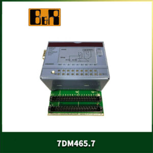
Every plant running System 2003 is sitting on a spare-parts clock. The 7DO135.70 is the module that keeps those machines alive — a screw-in digital output card with 4 FET channels, 12–24 VDC, 0.1 A, mounted on a TB712 terminal board. It drives relay coils, solenoid valves, indicator lamps. Nothing exotic. That’s exactly why it’s worth stocking.Engineers pick it for two reasons the spec sheet doesn’t shout about. First, the conformal coating: this board passed the BMW GS 95011-4 condensation test and meets EN 60068-2-60 corrosive gas requirements, so it survives a humid paint shop or a chemical plant mezzanine without a separate enclosure. Second, TPU mode — the outputs can be driven directly by B&R’s real-time processor, bypassing the normal PLC scan cycle. If you need a fast interlock pulse, that’s where it comes from. My honest note: the module itself rarely dies. The failures I’ve traced were almost always at the terminal board — oxidized contacts, a loose 24 V feed, or a technician who swapped the card and never checked the wiring.
Quality SOP & Tech Pitfalls
The Lab Report (SOP)
- Visual and counterfeit check — nameplate photo, part number, date code, FET output terminals, connector inspection.
- Live test on a System 2003 test rack with a known-good CPU and a genuine TB712 terminal board.
- Channel-by-channel verification: standard on/off, PWM duty cycle and period, TPU output.
- Insulation resistance and 24 V continuity with a Fluke 115.
- Firmware/revision and serial number logged on the packing list.
- Anti-static bag, foam pack, outer box marked “Precision Instrument — Do Not Drop.”
The Engineer’s Warning (Pitfalls)Mistake one: buying the module without the TB712 terminal board. It’s a screw-in module and the terminal board is a separate order. I’ve watched a plant sit idle three extra days because the card arrived and the board didn’t.Mistake two: not recording the original channel mode before the swap. Standard, PWM, and TPU behave completely differently. Drop in a new card configured as standard when the old one was running PWM, and the output won’t fault — it just won’t do what the machine expects. I once spent four hours chasing an “intermittent” fault on a packaging line. The previous technician had replaced the module and left it in default mode. The old card was fine.
Installation & Configuration Guide
Phase 1 — Pre-Installation (⚠️)
- ⚠️ Put the machine in a safe state. Stop the CPU, cut module power, apply lockout/tagout.
- ⚠️ Wait 60 seconds for bus capacitance to discharge before touching terminals.
- ⚠️ Photograph the old channel configuration (standard/PWM/TPU), terminal wiring, and rack slot. Two angles each.
Phase 2 — Removal
4. Label every output wire by channel (1–4) and the 24 V supply with tape and a marker.
5. Release the screw-in fastening and pull the module straight out. Do not pry against the terminal board.
6. Inspect the TB712 terminals for oxidation or burn marks. Clean or replace if found.Phase 3 — Installation
7. Confirm the TB712 terminal board is present and in good condition, then seat the new module fully. This single check prevents most startup failures.
8. Restore output wires and 24 V per your labels. Torque terminal screws to spec.Phase 4 — Power-On & Testing
9. Restore power. Confirm module voltage sits inside 12–24 VDC.
10. In the configuration software, verify the module is recognized and the channel mode matches the original.
11. Force-test each channel: standard on/off, PWM waveform, TPU output if used.
12. Run at reduced load for 30 minutes before returning to production.

Compatible Replacement Models
| Tier | Model | Notes |
|---|---|---|
| ✅ Drop-in Replacement | 7DO135.70 (same part) | 100% hardware/software match. New-surplus pricing varies widely — confirm condition and revision before payment. |
| ⚠️ Software Compatible | 7DO135.70, different date code | Same part; may require re-downloading the channel configuration. Budget 1–2 hours of labor. |
| ❌ Hardware Mod Required | X20 series digital output modules (X20DO family) | Different platform — new rack, new terminal boards, full reconfiguration. Only sensible as part of a planned system upgrade, not an emergency repair. |
Frequently Asked Questions (FAQ)
Can I hot-swap this safely?
No. Cut module power and lock out first. Hot-plugging a FET output module under load can kill the output stage or the connected load.Do I really need the TB712 terminal board?
Yes. It’s a screw-in module and the terminal board is ordered separately — it does not ship with the card.If the new module powers up but the outputs don’t work, is it defective?
Nine times out of ten, no. Check the channel mode in the configuration first (standard vs. PWM vs. TPU), then the 24 V feed, then the terminal board. Only after those three should you suspect the card.Can it drive a 220 VAC load?
It cannot. This is a 12–24 VDC, 0.1 A FET output. Any AC or high-power load needs an interposing relay.Is new stock still available from B&R?
System 2003 is discontinued. Anything listed as “new” today is new-surplus or refurbished. Ask for a nameplate photo and date code before you pay.What does the warranty cover?
New-surplus units carry 12 months from shipment. Refurbished units carry a shorter term and will be labeled as such. Misuse, overvoltage, and wiring errors are excluded. The OEM manual has the final say on any spec dispute.