 Tel:
Tel:  Email:
  WhatsApp:
 Description
Key Technical Specifications
| Parameter | Specification |
|---|---|
| Mounting Style | DIN Rail (35mm) or Panel Mount |
| Terminal Type | Screw Clamp |
| Pin Configuration | 11-Pin Octal (Standard 8-pin + 3 auxiliary) |
| Current Rating | 10 Amps |
| Voltage Rating | 300V AC / 300V DC |
| Wire Size (Stranded) | 0.2 to 2.5 mm² (24 to 12 AWG) |
| Torque Rating | 0.5 to 0.6 N·m (4.4 to 5.3 lb-in) |
| Material | Thermoplastic (UL 94 V-0) |
| Operating Temperature | -40°C to 60°C (-40°F to 140°F) |
| Compatibility | 700-HA, 700-HC, 700-HN Relays & Timers |
Product Introduction
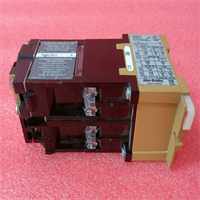
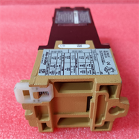
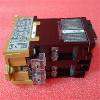
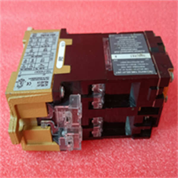
The Allen-Bradley 700-PKT B A-B is an 11-pin octal socket designed to interface industrial relays and timing modules with control panel wiring. It provides a secure mechanical and electrical connection for the 700-series relay family, allowing for quick component replacement without disturbing the field wiring.This socket supports a maximum current of 10A at 300V, making it suitable for standard control circuit loads. Unlike basic 8-pin sockets, the 700-PKT B includes three additional terminals (pins 9, 10, and 11) used for specific timer functions or relay isolation. It snaps directly onto a standard 35mm DIN rail or can be screw-mounted to a backplate.
Installation & Configuration Guide
Phase 1: Preparation (5 min)
- Verify the incoming unit matches the 700-PKT B A-B labeling.
- Ensure the DIN rail is grounded and de-energized.
- Gather a flat-head screwdriver (blade width 3.5mm recommended).
Phase 2: Mounting (2 min)
- DIN Rail: Hook the top of the socket onto the rail and press the bottom until the spring latch clicks.
- Panel Mount: Use two M3.5 or #6 screws through the mounting tabs on the side. Torque to 1.2 N·m.
- Note: If removing the unit later, insert a flat-head screwdriver into the release slot at the bottom and pull down gently.
Phase 3: Wiring (10 min)
- Strip wire insulation to 7mm (0.28 in).
- Insert wire into the terminal block.
- Tighten the screw to 0.5 – 0.6 N·m.
- Tug Test: Gently pull each wire to confirm it is clamped.
- Warning: Do not exceed 10A total current across the socket contacts.
Phase 4: Relay Insertion & Test (3 min)
- Align the relay pins with the socket holes.
- Push the relay straight down until it seats fully.
- If the relay has a hold-down clip, rotate it to lock the relay in place.
- Apply power and verify control logic operation.
Troubleshooting Quick Reference
| Symptom | Probable Cause | Corrective Action |
|---|---|---|
| Relay chatters or drops out | Loose terminal connection | Re-torque all screw terminals to 0.5 N·m. |
| No power to load | Blown fuse or broken wire | Check continuity across the common terminal. |
| Socket feels hot (>50°C) | Overloaded circuit | Measure current; ensure load is <10A. Check for loose wires causing resistance. |
| Timer function fails | Wrong pin usage | Verify wiring on pins 9, 10, 11 (auxiliary pins). |
| Relay won’t seat | Bent pins | Inspect socket interior. Do not force the relay. |
Dimensions, Mounting & Wiring Notes
- Dimensions: Approximately 78mm (H) x 35mm (W) x 60mm (D).
- Mounting: Compatible with standard 35mm DIN rails (IEC 60715).
- Terminal Identification: Pin numbers are molded into the plastic face of the socket.
- Wiring Note: When wiring the 11-pin configuration, ensure you are using a relay that actually utilizes pins 9, 10, and 11. Standard 8-pin relays will leave these terminals unused.
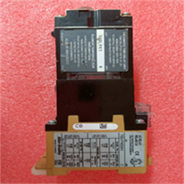
700-PKT B A-B
FAQ
Will this socket fit a standard 8-pin relay?
Yes. The 700-PKT B accepts standard 8-pin octal relays. The extra three pins (9, 10, 11) will simply remain empty if you use a standard relay.I need a socket for a 700-HN104. Is this the same?
The 700-PKT B is the direct functional equivalent and replacement for the older 700-HN104 socket style. It fits the same footprint and pinout.What is the difference between the 700-PK and 700-PKT?
The “T” usually denotes specific terminal arrangements or slight molding updates in the 700 series, but electrically they are generally interchangeable for standard relay mounting. The 700-PKT B is the modern standard for this form factor.Can I mount this directly to a metal plate without a DIN rail?
Yes. There are two mounting holes on the side flanges of the socket body designed for #6 or M3.5 screws.Is this item new or used?
We list this as New Surplus. It is an original Allen-Bradley part that has been in storage. It has not been installed in a machine, though the box may show shelf wear.What wire size should I use?
You can use anything from 24 AWG up to 12 AWG. If you are using 10 AWG solid wire, it might be a tight fit in the clamp, so 12 AWG stranded is the sweet spot for easy installation.