 Tel:
 Email:
 WhatsApp:
Description
Key Technical Specifications
| Parameter | Specification |
|---|---|
| Power Supply | 24 V DC (18–36 V range) |
| Power Consumption | 8 W (at 24 V) |
| Load Cell Inputs | 2 channels (Pressductor compatible) |
| Excitation Signal | 0.5 A rms, 330 Hz |
| Analog Output 1 | -5 to +11 V (Max load 5 mA) |
| Analog Output 2 | 0 to 21 mA (Max load 550 Ω) |
| Fieldbus | PROFIBUS DP (Integrated) |
| Display | 2×16 character multi-language LCD |
| Mounting | DIN Rail (IP20 protection) |
| Operating Temp | -20°C to +50°C (Typical) |
| Weight | Approx. 120 g |
| Dimensions | 170 x 105 x 32 mm |
Product Introduction
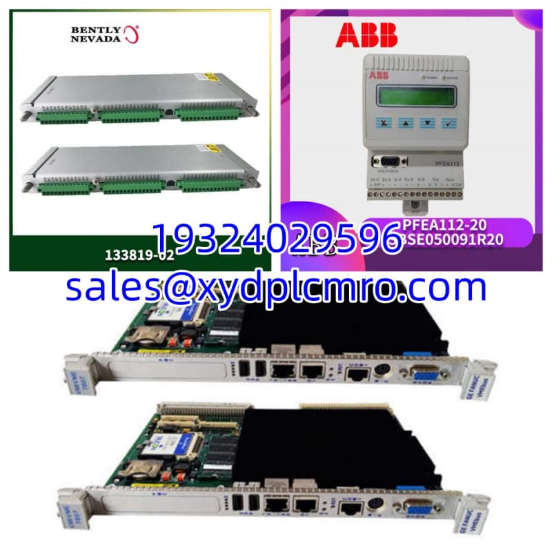
If you’ve ever tried to maintain constant tension on a high-speed slitter with a standard analog amplifier, you know the pain of signal drift and noise. The ABB PFEA112-20 fixes this by acting as a dedicated interface between your Pressductor load cells and the PLC. It’s not just an amplifier; it’s a signal conditioner that filters out the mechanical vibration noise that plagues dirty factory floors. I’ve seen these running on paper mills for decades without a hiccup, provided you keep the power supply clean.What makes the PFEA112-20 a staple in my spares inventory is the integration. You get dual load cell support and PROFIBUS DP communication in a compact DIN-rail package. It handles the excitation (330 Hz) internally, which simplifies wiring significantly compared to older relay-logic setups. The 2×16 display is surprisingly useful for troubleshooting—you can view the sum, difference, or individual load cell values right at the cabinet without hooking up a laptop. Just a heads-up: this specific revision is strictly IP20, so keep it in a clean cabinet, unlike its sealed IP65 siblings.
Quality SOP & Tech Pitfalls
The Lab Report (SOP)
Before this module goes into a box, it goes through my standard bench verification:
- Visual Inspection: I check the DIN clip integrity and terminal block for stress cracks.
- Bench Test: Powered via a regulated Fluke 115 supply. I verify the 24V input draws correct current (~8W).
- Excitation Check: Scope the output to the load cell terminals. It must show a clean 330 Hz sine wave. If it’s distorted, the unit is rejected.
- Communication Test: Connected to a test PLC via PROFIBUS to verify the GSD file handshake and data exchange.
- Sealing: Anti-static bagging with desiccant.
The Engineer’s Warning (Pitfalls)
- The “Ghost” Tension Reading: I once spent hours chasing a “bad” PFEA112 because the tension reading was fluctuating wildly. The culprit? The shield on the load cell cable wasn’t grounded at the sensor end, acting as an antenna for VFD noise. Always verify your grounding strategy per the manual.
- Configuration Key Mismatch: Swapping this unit without a configuration key (or copying parameters) is a recipe for disaster. The internal scaling parameters are unique to your load cells. If you drop in a new module without transferring the calibration data, your tension readings will be garbage, potentially snapping your web.
Installation & Configuration Guide
- Pre-Installation:
- ⚠️ Lockout/Tagout the 24V DC supply.
- If replacing a faulty unit, remove the configuration key (if equipped) or photograph the existing parameter settings immediately.
- Removal:
- Label the load cell cables (A and B) clearly. They are not interchangeable.
- Release the DIN rail clip and pull the module straight out.
- Installation:
- Snap the new PFEA112-20 onto the DIN rail.
- Insert the configuration key or manually enter the scaling parameters (Zero and Span) to match your load cells.
- Torque terminals to 0.5 Nm. Don’t strip them.
- Power-On & Testing:
- Restore 24V power. The display should light up.
- Check the “Status” LED. Green is good; Red means check the error code on the display.
- Verify the PROFIBUS “Com” LED is flashing (indicating data exchange) and not solid red (bus fault).
Compatible Replacement Models
| Compatibility | Model | Notes |
|---|---|---|
| ✅ Drop-in Replacement | PFEA112-65 | Same electronics, but sealed IP65 housing. Requires different mounting (screws, not DIN rail). |
| ⚠️ Software Compatible | PFEA111-20 | Lacks PROFIBUS DP. Only use if you are hardwiring analog outputs only. |
| ❌ Hardware Mod Required | PFEA113-20 | Supports 4 load cells and has more I/O. Requires rewiring and new GSD file in PLC. |
| ❌ Hardware Mod Required | PFEA122 | Uses PROFINET/EtherNet/IP instead of PROFIBUS. Not a direct swap for DP networks. |
Frequently Asked Questions (FAQ)
Q: Can I use this with any load cell?
A: No. The PFEA112-20 is designed specifically for ABB Pressductor sensors (PFCL, PFTL, PFRL series). It uses a 330 Hz excitation signal. Standard strain gauge load cells will not work with this amplifier.Q: What is the difference between 3BSE050091R20 and 3BSE030369R20?
A: They are functionally identical PFEA112-20 units. The part number change usually indicates a revision or packaging update from ABB. The -20 suffix confirms it is the IP20 DIN-rail version.Q: My display shows “E101”. What does that mean?
A: That’s typically a load cell error. It usually means one of the sensors is disconnected, the cable is broken, or the signal is out of range. Check your physical connections at the terminal block first.Q: Does this unit support hot-swapping?
A: While the hardware allows it, I advise against it. Pulling the module while the PLC is polling the PROFIBUS address can cause bus faults or trip the system. Swap it during a planned stop.Q: Can I calibrate this without a PC?
A: Yes. The front panel keys and display allow you to perform a zero and span calibration manually. You just need a known weight or a way to simulate tension.Q: Is the configuration key included?
A: Usually, no. The configuration key is a separate accessory. If you are replacing an old unit, you must move the key from the old module to the new one to retain settings, or manually re-enter them.