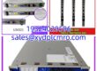
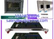
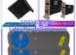
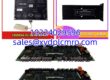
Key Technical Specifications
- Product Model: 853-049542-173
- Manufacturer: LAM RESEARCH
- Board Type: NODE BOARD, 24 CH TEMP CTLR
- Control Type: Control Type 3
- Channel Count: 24 Independent Temperature Control Channels
- Associated P/N: 810-028295-173
- System Integration: Lam Research Etch/Deposition Tool Node Architecture
- Function: Precision Thermal Management & Process Stability
- Form Factor: Standard Lam Research Node Board PCB
- Application: Semiconductor Etch Chamber Thermal Control
Product Introduction
Thermal runaway in an etch chamber doesn’t just scrap a wafer; it can cook a $200,000 chamber liner and halt production for days. The 853-049542-173 is the 24-channel temperature controller node that prevents this. It sits in the Lam Research tool’s node architecture, constantly reading thermocouples and adjusting heater zones to keep the process window dead-center. When this board drifts, your uniformity goes to hell, and you won’t see it until the SPC charts start screaming.I’ve replaced dozens of these in 300mm fabs. They are workhorses, but they are not magic. The Control Type 3 designation matters because the firmware and heater drive logic differ from Type 2 boards. This specific revision handles the thermal mass of modern multi-zone chucks well, but it demands clean power and solid thermocouple connections. If your TC wiring is noisy, this board will chase ghosts and oscillate the heaters until something fails.
Quality SOP & Tech Pitfalls
The Lab Report:
Semiconductor boards don’t fail like PLCs; they drift. Our validation for 853-049542-173 is specific:
- Visual & Micro-Solder Inspection: We check the high-current heater drive traces and MOSFETs for thermal stress or micro-cracks.
- Channel Calibration Check: We simulate 24 thermocouple inputs and verify the ADC reading matches within ±0.5°C.
- Output Drive Test: We load each channel to verify the PWM drive signal is clean and not clipping.
- Firmware/Config Verification: We read the onboard EEPROM to confirm it matches the 810-028295-173 configuration profile.
- ESD & Moisture Seal: Packed in vacuum-sealed ESD shielding with humidity indicator cards.
The Engineer’s Warning:
Here is the classic trap: Thermocouple Polarity & Noise. This board expects clean mV signals. I’ve seen techs use unshielded wire for the TC extension, and the 60Hz noise from the chamber RF match network coupled right into the input. The 853-049542-173 tried to compensate, ramped the heater to 100%, and melted the O-ring. Also, never swap this board without checking the Control Type jumper or EEPROM config. A Type 3 board in a Type 2 slot will try to drive heaters with the wrong PID constants. Result? Thermal oscillation and scrapped wafers.
Installation & Configuration Guide
- Pre-Installation Safety: ⚠️ LOCKOUT/TAGOUT. Verify chamber is at atmospheric pressure and <40°C. Disconnect the 24V DC node power. Wait 5 minutes for heater capacitors to discharge.
- Documentation: PHOTO EVERYTHING. Before pulling the old board, photograph the DIP switches, jumper blocks, and the ribbon cable orientation. Write down the serial number and firmware version from the label.
- Removal: Disconnect the thermocouple ribbon and heater drive cables first. Release the node board ejectors. Pull straight out. If it binds, stop. Bent pins on the backplane are a nightmare to fix.
- Configuration Transfer: MATCH ALL JUMPERS/DIP SWITCHES. This is non-negotiable. The 853-049542-173 uses these for node addressing and heater type selection. Copy them exactly.
- Installation: Seat the new board firmly. Reconnect the TC ribbon before the heater cables. Verify pin 1 alignment.
- Power-On & Verify: Restore node power. Watch the node status LED. You should see a solid green or specific boot code. Run the Heater Open/Short Test from the service menu before enabling auto-control. If it fails, check your wiring. Do not proceed.
Compatible Replacement Models
| Status | Model | Notes |
|---|---|---|
| ✅ Drop-in Replacement | 853-049542-173 | Exact match. Verify Control Type 3 and firmware rev. |
| ⚠️ Software Compatible | 853-049542-174 | Same hardware family, different channel calibration or firmware. Requires service menu reconfiguration. |
| ❌ Hardware Mod Required | 853-049542-002 | Earlier revision. Missing newer thermal protection logic. Do not use in modern etch chambers without OEM engineering approval. |
Frequently Asked Questions
Can I use a 853-049542-174 instead of the -173?
Maybe, but it’s risky. The -174 is often a later revision with updated PID tables or safety limits. If you swap it in, you must run the auto-tune routine and verify the heater response in manual mode first. I’ve seen -174s work fine in -173 slots, but also seen them trigger false over-temp faults because the alarm threshold was tighter. Check the Lam Research Service Bulletin for your specific tool serial number.Why is my new board showing “TC Open” on all channels?
You likely didn’t seat the ribbon cable fully, or you bent a pin. This board uses high-density connectors that are unforgiving. Pull it, inspect the pins with a flashlight, and reseat with firm, even pressure. If it persists, check the TC wiring at the chamber feedthrough. I’ve seen broken wires inside the insulation from years of thermal cycling.Is this board sensitive to ESD?
Extremely. The front-end ADC and heater drive MOSFETs are exposed. If you touch the board without a grounded wrist strap, you might not kill it immediately, but you can degrade the input protection diodes. Six months later, it starts drifting. Treat it like a raw egg.How do I know if the Control Type is correct?
Look at the label. It must say Control Type 3. If you have a Type 2 board in the system, this 853-049542-173 will not work correctly. The heater drive frequency and feedback loop are different. Don’t guess. Verify against the tool’s configuration sheet.Can I repair this if a heater channel is shorted?
Technically, yes. Practically, no. The heater drive circuit is integrated, and the board is often conformal coated. Finding the shorted MOSFET without lifting the coating is a gamble. The cost of a verified 853-049542-173 is less than 4 hours of senior engineer time plus the risk of a bad repair. Swap it.Does this board store calibration data?
Yes, in EEPROM. If you replace it, you usually need to download the calibration constants from the host controller or run a full system calibration. Don’t assume it’s “plug and play” for process quality. It’s plug and play for communication, but thermal accuracy requires validation.