 Tel:
Tel:  Email:
  WhatsApp:
 Description
Key Technical Specifications
| Parameter | Specification |
|---|---|
| Total Channels | 36 (4 dedicated, 32 defined by I/O module) |
| Terminal Type | Screw terminals |
| Wire Gauge | 16–26 AWG |
| Max Voltage | 250 V (channel-to-ground, CAT II) |
| Max Current | 10 A (limit per terminal) |
| Compatibility | All FieldPoint I/O modules (except dual-channel series) |
| Mounting | DIN rail or panel mount |
| Operating Temp | -40 to 70 °C |
| Storage Temp | -55 to 85 °C |
| Weight | 7.4 oz (approx. 210 g) |
Product Introduction
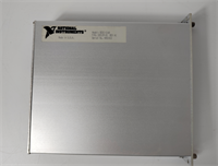
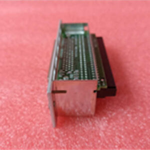
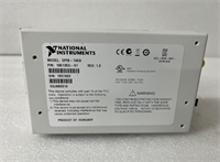
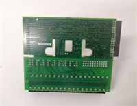
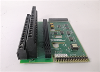
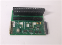
The NI FP-TB-1 is a universal terminal base designed for the FieldPoint I/O system, providing the physical interface for field wiring. It features 36 screw terminals to connect sensors, actuators, and power, forming the local bus that supplies power and communication to the attached I/O modules. This base is the standard mounting solution for most FieldPoint applications, excluding those requiring dual-channel modules.It supports a wide range of industrial wiring with 16–26 AWG copper wire and handles voltages up to 250 V (CAT II). The design allows for easy maintenance, as the terminal block can be removed for检修 without disturbing the field wiring. Its rugged construction and wide operating temperature range (-40 to 70 °C) make it suitable for harsh industrial environments.
Installation & Configuration Guide
Preparation (10 min)
- Ensure the power supply to the FieldPoint network is OFF and locked out.
- Verify you have the correct I/O module for your application.
- Prepare your field wires, stripping 16–26 AWG insulation as needed.
Removal (N/A – New Install)
- Note: If replacing an old base, disconnect all field wiring and remove the old unit from the DIN rail or panel.
Installation (10 min)
- Clip the FP-TB-1 onto a standard DIN rail or secure it to a panel using the mounting holes.
- Lock the base in place using the interlocking design.
- Insert the FieldPoint I/O module into the terminal base until it clicks.
- Connect your field wires to the appropriate screw terminals.
Power-On & Test (10 min)
- Double-check all wiring connections for tightness and correct placement.
- Restore power to the system.
- Verify communication with the I/O module through your controller software (e.g., LabVIEW, MAX).
Troubleshooting Quick Reference
| Symptom | Probable Cause | Corrective Action |
|---|---|---|
| Module Not Detected | Module not fully seated. | Power off, remove, and re-insert the I/O module firmly. |
| Noisy Signal | Poor grounding or wire gauge. | Verify ground connections; ensure wire is 16–26 AWG copper. |
| Terminal Overheating | Current exceeds 10 A. | Measure current draw; ensure it is within the 10 A limit. |
| Wrong Channel Count | Incompatible module used. | Confirm the I/O module is not a “dual-channel” series type. |
Dimensions, Mounting & Wiring Notes
- Dimensions: 4.2 x 4.3 x 3.6 inches.
- Mounting: Standard 35 mm DIN rail or direct panel mount.
- Wiring: Use copper wire only (unless using thermocouples). Strip insulation carefully to avoid short circuits.
- Note: The terminal block is removable for easy service.
FP-TB-1 NI
FAQ
What wire size should I use?
Use standard 16–26 AWG copper wire. Strip the insulation cleanly to ensure a good connection in the screw terminals.Can I mix different I/O modules on this base?
Yes, you can mix most FieldPoint I/O modules on the same FP-TB-1 base, but you cannot use the dual-channel series modules.Is this base compatible with thermocouples?
Yes, but for thermocouple applications, NI recommends the FP-TB-3 base which is optimized for that module type.How do I know if my module is a “dual-channel” type?
Check the module label. The FP-TB-1 is not compatible with modules specifically designated as “dual-channel” series.What is the maximum voltage rating?
The base is rated for 250 V (channel-to-ground, CAT II). Do not exceed this limit to avoid damage or safety hazards.