 Tel:
Tel:  Email:
  WhatsApp:
 Description
Key Technical Specifications
| Parameter | Specification |
|---|---|
| Architecture | TMR (Triple Modular Redundancy) or Dual Redundant |
| Processor | 32-bit RISC (e.g., Intel 386EX or ARM Cortex-A9) |
| Safety Rating | IEC 61508 SIL 3 (Systematic Capability SIL 4) |
| Memory | 1 MB Flash-EPROM (Program), 1 MB SRAM (Data) |
| Operating Temp | -20°C to +60°C (Industrial Grade) |
| Supply Voltage | 24V DC (Redundant Power Inputs) |
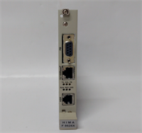
| Communication | HIMax Bus, Ethernet (Service Port) |
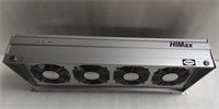
| Weight | Approx. 0.4 kg |
Product Introduction
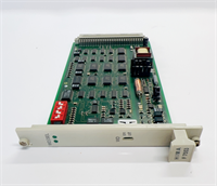
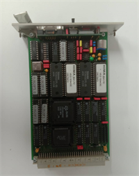
The HIMA F8620/11 is not your average PLC processor; it is a dedicated safety controller designed to keep high-risk industrial processes from turning into fireballs. Whether you are running a burner management system in a power plant or an emergency shutdown (ESD) loop in a refinery, this module is the brain that decides when to kill the process to save lives and equipment.I have seen these modules sitting in control cabinets covered in dust, vibrating next to massive turbines, and they just keep ticking. The “11” suffix usually denotes a specific hardware revision within the HIMax family, often featuring dual or triple microprocessor channels that constantly compare data to catch errors before they affect the output. It’s old-school reliability—robust memory protection, battery-backed RAM, and a form factor that fits standard HIMA racks. If you are maintaining a legacy HIMA system, this card is the heartbeat of your safety loop.
Quality SOP & Tech Pitfalls (The Reality Check)
The Lab Report (SOP)
We don’t trust “New Old Stock” blindly. Here is how we validate an F8620/11:
- Visual Inspection: We check the PCB for corrosion, specifically around the edge connectors and the battery holder. Leaking batteries are the #1 killer of these boards.
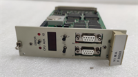
- Internal Self-Test: Upon applying 24V DC, the module runs a proprietary self-diagnostic routine. We monitor the LED status codes to ensure the CPUs, memory, and comparators pass.
- Communication Handshake: We connect via the service port (often RS232 or Ethernet depending on the sub-revision) to verify the module responds to the engineering workstation software (ELOP II or SafeWare).
- Memory Verification: We verify the checksum of the loaded firmware to ensure it hasn’t degraded over time.
️ The Engineer’s Warning (Pitfalls)
Watch out for the Battery. This module uses a battery to retain RAM data (user programs and configuration) when power is removed. If you pull this card out of a live rack without ensuring the battery is good, or if you leave it unpowered for too long, you will lose your program. Always have a backup of your logic before touching this card.Also, do not mix revisions carelessly. The F8620/11 has specific timing requirements. Swapping it into a chassis with older backplane modules or incompatible power supplies can cause synchronization faults in the TMR architecture. Verify your chassis compatibility.
️ Installation & Configuration Guide
Phase 1: Pre-Installation
⚠️ Safety First: This is a safety-critical component. Ensure you have bypassed the logic in the software or obtained a work permit before removing the card to prevent a nuisance trip.
- Photo Documentation: Take a picture of the DIP switches or jumpers on the faceplate. These settings control termination and addressing.
- Check Redundancy: If running in a redundant pair/triplet, verify the status of the partner modules.
Phase 2: Removal
- Disconnect any external cables (Ethernet/Serial) if they block removal.
- Unlock the DIN rail clip or chassis latch.
- Pull the module straight out. Do not twist it; the backplane pins are fragile.
Phase 3: Installation
- Copy Settings: Set the DIP switches/jumpers on the new module to match the old one exactly. This is where 90% of startups fail.
- Seat the Module: Slide it into the slot until it clicks firmly onto the backplane.
- Reconnect Cables: Plug in your service/ethernet cables.
Phase 4: Power-On & Testing
- Apply power.
- LED Sequence: Watch the boot sequence. You should see a flash of diagnostics followed by a steady “Run” or “OK” LED.
- Load Logic: If the card is blank, you will need to download the safety logic from your engineering station.
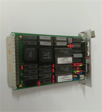
F8620 11 HIMA
Compatible Replacement Models
| Model | Compatibility Tier | Notes |
|---|---|---|
| F8620/11 | Exact Match | Standard revision for HIMax/HIQuad systems. |
| F8620 | Variant | Base model number; verify suffix compatibility. |
| F8652E | Upgrade/Newer Gen | Newer HIQuad CPU. Requires chassis verification and likely firmware migration. |
Frequently Asked Questions (FAQ)
Q: What does the “/11” mean in F8620/11?
A: It indicates the specific hardware revision or version of the processor module. In HIMA’s coding, this often relates to the processor speed, memory size, or communication interface capabilities. Always try to match the suffix when replacing.Q: Can I hot-swap this module?
A: Generally, yes, HIMA systems support hot-swapping of components to maintain availability. However, you must verify that the system is in a state where a module removal won’t trigger a safety action (trip). Consult your system manual regarding “Online Replacement” procedures.Q: My LED is flashing red. What does that mean?
A: A red LED usually indicates a hardware fault or a synchronization error between the redundant processors. It could also mean the internal self-test failed (e.g., memory parity error). You will need to connect the engineering tool to read the specific diagnostic buffer.Q: Is this module programmable?
A: Yes, but only using HIMA’s proprietary engineering software (like ELOP II or SafeWare). You cannot program it with standard ladder logic editors like Rockwell or Siemens.Q: Does this support Ethernet?
A: Most F8620/11 units have a service port that supports Ethernet or a proprietary bus for connecting to the operator station or engineering laptop. Check the front plate connectors to confirm the physical interface.