Tel:
Tel:  Email:
  WhatsApp:
 Description
⚙️ Key Technical Specifications
| Parameter | Specification | Notes |
|---|---|---|
| Output Channels | 2 Discrete Analog Outputs | Fully isolated |
| Signal Type | Current / Voltage | Software selectable per channel |
| Current Range | 0/4 … 20 mA | Max load ~500 Ohms |
| Voltage Range | 0 … 5 V / 0 … 10 V | Min load > 1 kOhm |
| Resolution | 12 Bit | 1 LSB ≈ 5 µA or 2.5 mV |
| Accuracy | ± 0.1% of Full Scale | Typical at 25°C |
| Conversion Time | < 5 ms | Per channel update |
| Safety Integrity | SIL 3 / AK6 | TÜV Certified |
| Supply Voltage | 24 V DC (Internal Bus) | Powered via backplane |
| External Power | Not Required | Loop powered or sourced |
| Operating Temp | -20°C to +60°C | Derate above 50°C |
| Dimensions | Standard HIMatrix Slot | Eurocard form factor |
👷 Product Introduction
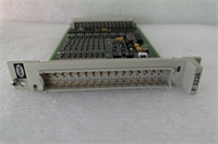
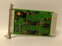
In the world of safety systems, Digital I/O gets all the glory for tripping the shutdown, but Analog Output is where the real finesse happens. The HIMA F6706 is the card you install when you need to precisely control a variable—like ramping down a compressor speed or modulating a fuel gas valve—rather than just slamming it shut. It’s a dual-channel, 12-bit output module that lives inside the HIMatrix or H41/H51 racks.What makes this module distinct is its dual-mode capability. You can configure Channel A for current (0-20mA) to drive a standard I/P converter, and Channel B for voltage (0-10V) for an older actuator, all within the same footprint. It’s built to the rigorous SIL 3 standard, meaning it performs internal self-diagnostics to ensure the signal it thinks it’s sending is actually the signal appearing at the terminals. If the wire breaks or the load impedance is too high, this card will tell you immediately. It’s not the newest tech on the block—12-bit is standard, not high-res—but for moving heavy industrial iron safely, it’s bulletproof.
🔍 Quality SOP & Tech Pitfalls (The Reality Check)
The Lab Report (SOP)
Analog cards are notoriously sensitive to calibration drift. We don’t just check if they turn on; we verify the math.
- Visual Inspection: We check the terminal block pins for bending. These connectors are fragile.
- Backplane Comms: We seat the card and verify it talks to the CPU. No “Module Missing” errors allowed.
- Loop Calibration Test: Using a Fluke 744 calibrator (or equivalent) on the input side (software forcing) and a precision multimeter on the output:
- Force 0% (4mA). Measure actual current. Must be within ±0.1%.
- Force 100% (20mA). Measure actual current.
- We check for linearity. If 50% isn’t exactly halfway between 4 and 20, the DAC chip is drifting.
- Open Circuit Detection: We intentionally disconnect the load to verify the module detects the “wire break” condition if that feature is enabled.
The Engineer’s Warning (Pitfalls)
Watch your Load Impedance.
The most common “failure” I see with the F6706 isn’t the card—it’s the field wiring. This module has a maximum compliance voltage. If you try to drive a 4-20mA signal through 1000 Ohms of resistance (long cable runs + solenoid coil), the card physically cannot push enough voltage to get the current up to 20mA. You’ll see the logic say “100% Output,” but the valve will only open 80%. Do the math on your loop resistance before blaming the card.
Field Disaster Story: A client in a refinery had a surge tank level controller that was oscillating wildly. They blamed the PID tuning. I went out there and found the F6706 output was fluctuating because the shielding on the analog cable wasn’t grounded. The 12-bit resolution was picking up 60Hz noise from a nearby motor starter. The card was fine; the installation was garbage. Always ground your shields at the cabinet end only.
🛠️ Installation & Configuration Guide
Analog work requires patience. A loose screw here means a vibrating needle on your control panel.
- Pre-Installation (Safety First)
- ⚠️ LOCK OUT / TAG OUT: Even though it’s low voltage, shorting the backplane power pins can fry the motherboard. Kill the rack power.
- Identify the Wiring: Are you using Current (I) or Voltage (V)? The terminal assignments might differ slightly depending on the specific wiring schematic (check the rear label or manual).
- Removal
- Unplug the front connector (the white plastic block).
- Unscrew the locking mechanism (usually a thumbscrew or lever) on the faceplate.
- Slide the module out gently.
- Installation
- Slide the new F6706 into the slot. Ensure it seats flush against the backplane.
- Lock the faceplate screw.
- Re-wire: Connect your field wires to the connector.
- For Current Mode: Ensure you are using the correct terminals (often labeled I+ and I-).
- For Voltage Mode: Use the V+ and Common terminals.
- Plug the connector back in. Tighten the terminal screws firmly.
- Power-On & Testing
- Restore power.
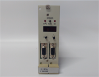
- Check LEDs:
RUNshould be Green.ERRshould be Off. - Force Output: Go into your engineering software (ELOP II) and force the output to 50% (12mA). Measure with a multimeter at the terminal block. If it reads 12mA, you’re golden.
F6706 HIMA
🔄 Compatible Replacement Models
HIMA part numbers can be tricky. Here is how the F6706 fits in the family.表格
| Model | Compatibility | Notes |
|---|---|---|
| F6706 | ✅ Drop-in Replacement | Standard 2-Ch Analog Output (12-bit). |
| F6705 | ⚠️ Pinout Match | Older revision/similar function. Verify wiring diagram before swapping. |
| F6217 | ❌ Input vs Output | This is an Analog Input module. Do not mix them up. |
| F3430 | ❌ Relay Output | This is a relay module, not analog. |
💬 Frequently Asked Questions (FAQ)
Q: Can I use this to drive a 0-10V motor drive?
A: Yes. The F6706 supports both current (0/4-20mA) and voltage (0-10V) outputs. You configure the mode in the hardware configuration software (ELOP II) before downloading to the controller.Q: Why is my output reading 0mA even though the logic says 50%?
A: Check for “Open Circuit.” If the wire is broken or disconnected, the module might cut output for safety. Also, verify you are measuring across the correct terminals (I+ and I-).Q: Is this module hot-swappable?
A: In a redundant TMR system (like H41q), yes, usually. However, pulling an analog card while the machine is running might cause a transient glitch in the output signal. If you are controlling a sensitive valve, put the loop in Manual mode first to freeze the output.Q: What does “12-bit resolution” mean for my control?
A: It means the 20mA range is divided into 4096 steps. Each step is about 5 microamps. For 99% of industrial valves and drives, this is plenty smooth. You won’t notice any “stair-stepping” in the movement.Q: Does it require an external power supply?
A: No. The module draws its operating power from the HIMatrix backplane. However, for 4-20mA loops, the module itself acts as the power source (sourcing current), so you don’t need an extra power supply for the loop unless you are using a specific 3-wire device.