

 Tel:
Tel:  Email:
  WhatsApp:
 Description
⚙️ Key Technical Specifications
| Parameter | Specification | Notes |
|---|---|---|
| Input Channels | 8 Discrete Analog Inputs | Software configurable |
| Signal Type | Current / Voltage | Auto-sensing or fixed |
| Current Range | 0/4 … 20 mA | Supports up to 22mA overload |
| Voltage Range | 0 … 5 V / 0 … 10 V | Input impedance 100 kΩ |
| Resolution | 12 Bit | 1 LSB ≈ 5 µA or 2.5 mV |
| Accuracy | ± 0.1% of Full Scale | Typical at 25°C |
| Sampling Time | ~50 ms | Per channel conversion |
| Isolation | Channel-to-System | Prevents ground loops |
| Safety Integrity | SIL 3 / AK6 | TÜV Certified |
| Supply Voltage | 24 V DC (Internal Bus) | Powered via backplane |
| Operating Temp | -20°C to +60°C | Derate above 50°C |
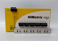
| Dimensions | Standard HIMatrix Slot | Eurocard form factor |
👷 Product Introduction
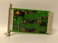
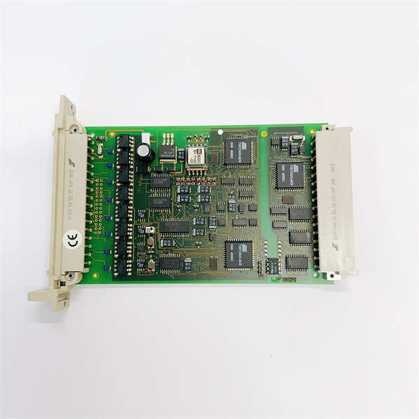
If you are running a chemical plant or a refinery, you don’t just need to know if a valve is open or closed—you need to know the exact pressure inside the vessel right now. That is where the HIMA F6217 comes in. It is an 8-channel analog input module designed specifically for safety-critical environments. It takes those standard industry signals (4-20mA from your transmitters) and converts them into digital data the safety controller can trust.What makes this module special is the redundancy and diagnostics. In a standard PLC, a bad wire might just read zero. In a HIMA system using the F6217, the module detects the wire break, flags a specific error code, and forces the system into a safe state without tripping the whole plant unnecessarily. It features 12-bit resolution, which gives you about 0.1% precision—more than enough to catch a runaway reaction before it becomes a headline. It’s rugged, it’s certified for SIL 3 applications, and it plays nice with both current and voltage sensors.
🔍 Quality SOP & Tech Pitfalls (The Reality Check)
The Lab Report (SOP)
Analog cards are finicky. We don’t just check if they turn on; we verify the signal path integrity.
- Visual Inspection: We check the connector pins. These modules use high-density connectors that bend easily if mishandled.
- Backplane Comms: We seat the card and verify it talks to the CPU. No “Module Missing” errors allowed.
- Precision Calibration Test: Using a Fluke calibrator, we inject precise signals:
- Inject 4.00 mA. Verify register reads ~20% (scaled).
- Inject 20.00 mA. Verify register reads ~100%.
- We check linearity. If 12mA doesn’t read exactly halfway, the A/D converter is drifting.
- Diagnostic Simulation: We intentionally short an input and leave one open to verify the module triggers the correct “Wire Break” or “Short Circuit” alarms in the software.
The Engineer’s Warning (Pitfalls)
Don’t leave channels floating.
The F6217 is sensitive to “ghost voltages.” If you have unused channels, do not just leave the wires hanging off the terminal block. You must terminate them (short them out or tie them to ground/common) according to the manual. An open, floating input can pick up electromagnetic interference (EMI) from nearby contactors, tricking the safety logic into thinking there is a high-pressure alarm when there isn’t one.
Field Disaster Story: I had a client in a power plant complaining that their temperature readings were “dancing” randomly. They replaced the F6217 twice. I went out there and found they were using unshielded cable for the thermocouple extension wires, running right next to a 480V motor feeder. The noise floor was so high the 12-bit converter was freaking out. We re-ran shielded cable, grounded the shield at the cabinet end, and the problem vanished. The card was fine; the installation was noisy.
🛠️ Installation & Configuration Guide
Analog work requires clean hands and tight screws. A loose connection here means a vibrating needle on your control panel.
- Pre-Installation (Safety First)
- ⚠️ LOCK OUT / TAG OUT: Kill the rack power. While it’s low voltage, shorting the backplane pins during insertion can fry the motherboard traces.
- Check Jumpers/Termination: If your system uses external termination assemblies, verify the wiring matches the schematic (Current vs. Voltage mode).
- Removal
- Unplug the front connector (the white plastic block).
- Unscrew the locking mechanism (usually a thumbscrew or lever) on the faceplate.
- Slide the module out gently.
- Installation
- Slide the new F6217 into the slot. Ensure it seats flush against the backplane.
- Lock the faceplate screw.
- Re-wire: Connect your field wires to the connector.
- For Current Mode (4-20mA): Ensure you are using the correct terminals (often labeled I+ and I-).
- For Voltage Mode: Use the V+ and Common terminals.
- Plug the connector back in. Tighten the terminal screws firmly.
- Power-On & Testing
- Restore power.
- Check LEDs:
RUNshould be Green.ERRshould be Off. - Verify Input: Go into your engineering software (ELOP II) and check the raw value. If you have 0 psi, does it read ~0%? If you have a known pressure, does the math match?
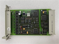
F6217 HIMA
🔄 Compatible Replacement Models
| Model | Compatibility | Notes |
|---|---|---|
| F6217 (984621702) | ✅ Drop-in Replacement | Standard 8-Ch Analog Input. |
| F6216 | ⚠️ Pinout Match | Older revision or different density. Verify wiring diagram. |
| F6706 | ❌ Output vs Input | This is an Analog Output module. Do not mix them up. |
| F3335 | ❌ Digital Input | This is a discrete input module. |
💬 Frequently Asked Questions (FAQ)
Q: Can I mix 4-20mA and 0-10V sensors on the same card?
A: Yes. The F6217 allows you to configure each channel individually via software. You can have Channels 1-4 wired for current loops and Channels 5-8 wired for voltage inputs. Just make sure your wiring matches the configuration.Q: Why is my “Error” LED flashing red?
A: It usually indicates a “Wire Break” (Open Circuit) or a “Short Circuit” on one of the active channels. Check your field wiring. If the sensor is disconnected, the module will flag it immediately as a safety precaution.Q: Is this module hot-swappable?
A: In a redundant TMR system (like H41q), yes, usually. However, pulling an analog card while the machine is running removes the monitoring for those points. If a fault occurs on that sensor while the card is missing, the system won’t see it. Proceed with caution.Q: What does “12-bit resolution” mean for my control?
A: It means the 20mA range is divided into 4096 steps. Each step is about 5 microamps. For 99% of industrial pressure and temperature transmitters, this provides smooth, stable control without “jitter.”Q: Does it require an external power supply?
A: No. The module draws its operating power from the HIMatrix backplane. For 4-20mA loops, the module typically acts as the power source (sourcing current) for 2-wire transmitters, so you don’t need an extra power supply for the loop itself.