 Tel:
Tel:  Email:
  WhatsApp:
 Description
Key Technical Specifications
| Parameter | Specification |
|---|---|
| Channels | 8 Independent Safety Outputs |
| Power Rating | 12 W per channel (Typical) |
| Voltage | 24V DC Nominal |
| Safety Level | IEC 61508 SIL 3 / Category 4 |
| Diagnostics | Open circuit & Short circuit detection |
| Status Indicators | Individual LED per channel |
| Load Type | Solenoids, Relays, Motors (Inductive loads) |
| Response Time | < 10ms (Typical trip time) |
Product Introduction
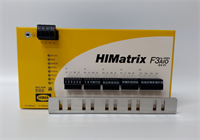
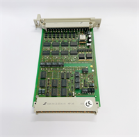
In a safety system, the CPU makes the decision, but the HIMA F3330 pulls the trigger. This is an 8-channel digital output module designed for one specific job: driving solenoids and relays when things go wrong. It’s not a standard PLC output card; it’s a “Safety Related” module rated for SIL 3 and Category 4 applications.I’ve used these in burner management systems where a failure to trip means an explosion. The F3330 is built to handle inductive loads (like solenoid valves) without needing external flyback diodes—it handles the back-EMF internally. A key feature I appreciate is that if you lose the module’s internal logic power, the outputs physically drop out. There’s no “ghost voltage” keeping a valve open when it should be closed. If you are maintaining a legacy HIMA Planar or Quadlog system, this card is your last line of defense.
Quality SOP & Tech Pitfalls (The Reality Check)
The Lab Report (SOP)
We don’t just check if the lights turn on. We test the safety features.
- Visual Inspection: We look for burnt traces near the output terminals—signs of a previous short circuit or arc flash.
- Output Force Test: We force each of the 8 channels ON and OFF via software while measuring the voltage at the terminal block. We verify the LED status matches the physical output state perfectly.
- Short Circuit Simulation: We briefly simulate a short on one channel to ensure the module detects it and latches/trips as designed without destroying the driver transistor.
- Backplane Comm Check: We verify the module communicates correctly with the HIMA CPU (HIMax bus) to ensure it receives trip signals instantly.
️ The Engineer’s Warning (Pitfalls)
Beware the “Parallel” wiring. The F3330 allows you to parallel outputs for higher current capacity (redundancy). However, if you wire this incorrectly—specifically if you cross the L+ feeds from different modules—you can backfeed voltage into a tripped module. This prevents the solenoid from de-energizing. Always verify your ring供电 (ring supply) wiring.Also, watch the fuses. While the module has electronic protection, there are often external or internal fusing links for the 24V feed. If the outputs aren’t firing, check the continuity of the power rail first.
Installation & Configuration Guide
Phase 1: Pre-Installation
⚠️ Safety First: De-energize the 24V field power. Even though it’s low voltage, solenoids can draw significant current, and shorting a live terminal can weld your screwdriver.
- Photo Documentation: Take a picture of the wiring. These modules often have complex commoning links for the 24V supply.
- Check Load Impedance: Ensure your solenoids/relays match the 12W rating. Overloading a channel will cause immediate faulting.
Phase 2: Removal
- Disconnect the field wiring harness.
- Release the DIN rail clip or chassis latch.
- Pull the module straight out.
Phase 3: Installation
- Seat the Module: Slide the F3330 into the slot. Ensure the backplane connector mates fully.
- Wire It Up: Reconnect the 24V supply and the load wires. Tighten terminals firmly—vibration loosens connections, leading to heat buildup.
- Verify Polarity: Double-check + vs -. While some inputs are protected, reversing power on outputs can be fatal to the card.
Phase 4: Power-On & Testing
- Apply power.
- LED Check: The module should perform a self-test. The “Module OK” light should be steady.
- Trip Test: Perform a partial stroke test or force an output ON to verify the solenoid clicks.
F3330 HIMA
Compatible Replacement Models
| Model | Compatibility Tier | Notes |
|---|---|---|
| F3330 | Exact Match | Standard 8-channel safety output. |
| F3331 | Variant | Usually differs in channel count or power rating. Check datasheet. |
| F3322 | Different Spec | Older revision or lower power rating. Verify load compatibility. |
Frequently Asked Questions (FAQ)
Q: What does “12 W” mean on the spec sheet?
A: It means each individual channel can safely switch up to 12 Watts of power. At 24V DC, that’s roughly 0.5 Amps per channel. If your solenoid draws 1 Amp, you cannot use this card directly (unless you use an interposing relay).Q: Can I hot-swap this module?
A: Generally, yes, HIMA systems support online replacement. However, removing this card cuts power to whatever safety devices it controls. You must bypass the logic or ensure the process is in a safe state before pulling the card, or you will cause a plant trip.Q: My LED is flashing red. What does that mean?
A: This indicates a “Wire Break” or “Short Circuit” alarm, or a mismatch between the commanded state and the read-back state. Check your field wiring for shorts to ground or open circuits.Q: Do I need external diodes for my solenoids?
A: No. The F3330 is designed to drive inductive loads directly. It has internal suppression circuitry. Adding external diodes is unnecessary unless specified by a specific retrofit guide.Q: Is this module obsolete?
A: It is considered legacy hardware. While HIMA supports these systems, finding brand-new stock is getting harder. Most available units are surplus or refurbished. Keep spares if you rely on them.