 Tel:
Tel:  Email:
  WhatsApp:
 Description
Key Technical Specifications
| Parameter | Specification |
|---|---|
| Part Number | F3322 |
| Channels | 16 Independent Digital Outputs |
| Voltage Rating | 24 VDC (Nominal) |
| Current Rating | 0.5 A per channel |
| Output Type | Open Collector or Push-Pull (Check Label) |
| Safety Level | SIL 3 (IEC 61508), suitable for SIL 4 applications |
| Protection | Short-circuit proof, Electronic fuse |
| Diagnostics | Per-channel LED status indicators |
| Power Consumption | ~12 W (Internal logic + load) |
| Communication | Internal HIMax Bus (Backplane) |
| Environment | -20°C to +60°C (Industrial Grade) |
Product Introduction
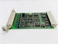
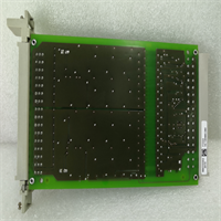
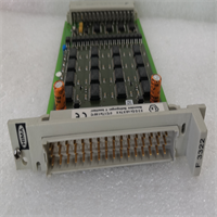
In a Safety Instrumented System (SIS), the CPU makes the decision, but the HIMA F3322 pulls the trigger. It’s the muscle that physically shuts down the process. You’ll find this card driving solenoid valves in ESD (Emergency Shutdown) systems or lighting up alarm beacons in BMS (Burner Management) setups.What sets the F3322 apart from a standard automation output card is the internal architecture. It’s designed to be “fail-safe.” If the module detects an internal fault—like a short circuit or a watchdog timeout—it can force the outputs to a safe state (usually de-energized) independent of the CPU. It handles 0.5A per channel, which is enough for most industrial solenoids, but if you are driving big contactors, you better use intermediate relays. It’s built like a tank, but don’t let that make you sloppy with the wiring.
Quality SOP & Tech Pitfalls (The Reality Check)
The Lab Report (SOP)
Before I sign off on an F3322, I put it through a rigorous bench test. Visuals aren’t enough.
- Visual Inspection: Check the backplane pins. These modules slide into a live backplane, and bent pins are the #1 cause of “ghost” faults.
- Power Up: Insert into a test rack. Verify the “Module OK” LED lights up green.
- Channel Test: Force all 16 outputs ON via software. Measure voltage at the terminals. You want 24V DC (or close to it) on every pin.
- Short Circuit Sim: This is critical for safety modules. Momentarily short one output to ground. The module should detect it, trip the electronic fuse, and light a fault LED. Reset it and ensure it recovers.
- Leakage Check: With outputs OFF, measure leakage current. It should be negligible (<1mA). High leakage can keep sensitive solid-state devices “half-on.”
The Engineer’s Warning (Pitfalls)
The biggest mistake I see? Ignoring the Common Mode Voltage.Even though these channels are isolated from the logic, they often share common power rails internally or in the terminal assembly. If you mix voltages (e.g., feeding Channel 1 with 24V from Power Supply A and Channel 2 with 24V from Power Supply B) without checking the isolation specs, you can create ground loops that fry the backplane. Keep your power distribution clean. Also, watch out for inductive kickback. If you are driving large relays without flyback diodes, the voltage spikes can degrade the output transistors over time.
Installation & Configuration Guide
Swapping this module requires strict adherence to safety protocols. You are touching the wires that trip the plant.
- Pre-Installation ⚠️
- Bypass Logic: Put the associated logic points in “Maintenance Override” or “Force” mode to prevent an accidental trip during the swap.
- Documentation: Take a photo of the wiring. Label every wire. “Field Side” vs “System Side.”
- Removal
- Disconnect the field wiring harness or individual terminals.
- Unlock the module from the DIN rail or chassis slot.
- Slide it out gently. Do not wiggle it excessively; you don’t want to stress the backplane connectors of adjacent cards.
- Installation
- Set any hardware jumpers or DIP switches (if applicable for specific revisions) to match the old card.
- Slide the new F3322 into the slot. Ensure it seats firmly against the backplane.
- Reconnect the wiring. Torque the terminals to spec (usually 0.5-0.6 Nm).
- Power-On & Testing
- Remove the maintenance overrides.
- Monitor the LEDs. Green is good. Red indicates a channel fault or comms error.
- Perform a functional test: Trip the logic and verify the physical output activates the field device.
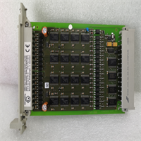
F3322 HIMA
Compatible Replacement Models
HIMA part numbers can be tricky. Stick to what you know works.
- ✅ Drop-in Replacement: F3322. Standard 16-channel digital output.
- ⚠️ Variant: F3322 (Push-Pull version). Some F3322s are Open Collector (sinking), others are Push-Pull (sourcing/sinking). Check the label. Using the wrong type will result in no output voltage.
- ❌ Wrong Type: F3330. This is an Analog Output module. It looks similar but won’t work for discrete on/off control.
Frequently Asked Questions (FAQ)
Can I hot-swap the F3322?
Technically, the HIMax system supports hot-swapping. However, removing the card breaks the connection to the field devices. If your system isn’t redundant (TMR or 1oo2), pulling this card will cause a loss of output. Always use Forced Outputs or Maintenance Overrides before pulling a safety card.Why is the “Fault” LED flashing red?
This usually indicates a short circuit on one of the 16 channels or an internal self-test failure. Check your field wiring for grounded wires. If the wiring is clear, the module’s output drivers might be damaged.What is the difference between Open Collector and Push-Pull?
Open Collector can only sink current (switch to ground); it needs an external pull-up resistor or source. Push-Pull can both source and sink current (active high and active low). Make sure your replacement matches your field device requirements.Does this module support SIL 4?
The F3322 is certified for SIL 3. However, when used in a redundant architecture (like a TMR system), the overall subsystem can achieve SIL 4 capability. The module itself is a building block for high-integrity safety loops.How do I reset a tripped electronic fuse?
Usually, once the short circuit condition is removed, the module resets automatically or via a software command from the engineering workstation (ELOP II). There is no physical fuse to replace; it’s solid-state protection.