

 Tel:
 Email:
 WhatsApp:
Description
Key Technical Specifications
| Parameter | Specification |
|---|---|
| Model | IS200VSVOH1BDC |
| Manufacturer | GE (General Electric) |
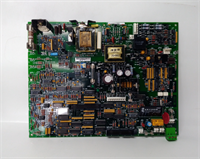
| Product Type | Servo control board (VSVO) for Mark VI / Mark VIe |
| System Family | GE Speedtronic Mark VI / Mark VIe |
| Servo Channels | 4 electro-hydraulic servo valve outputs (bidirectional current) |
| LVDT Support | Up to 6 LVDT position feedback inputs per servo loop |
| LVDT Function | Excitation output + position feedback for valve positioning |
| Pulse Rate Input | 2–14,000 Hz frequency range; supports passive/active speed sensors |
| Redundancy | Simplex and Triple Modular Redundant (TMR) configurations |
| Front Panel | J5 connector; RUN (green), FAIL (red), STATUS (orange) LEDs |
| Internal Connectors | P1/P2 (backplane), P3–P6 (I/O); JD1/JD2 (external trip) |
| Relays | K1–K4 (including suicide relay for safe output shutdown) |
| Terminal Boards | Interfaces with TSVO or DSVO servo terminal boards |
| Primary Application | Gas/steam turbine fuel and steam valve servo control |
| Operating Environment | Industrial turbine control cabinet; verify temperature per OEM datasheet |
Product Introduction
The IS200VSVOH1BDC is the servo workhorse inside a Mark VI turbine control rack. If you have ever stood in front of a gas turbine VME cabinet watching a servo valve drift off position while the RUN LED blinks green, you know this board is not something you substitute with a generic analog output card. It is a dedicated servo control board that executes closed-loop valve positioning using LVDT feedback and bidirectional servo current output.The VSVO board controls up to four electro-hydraulic servo valves simultaneously. Each channel can accept one to four LVDT sensors for valve position feedback, and the board provides the excitation voltage those LVDTs need. For flow measurement applications, it accepts pulse rate inputs in the 2–14,000 Hz range from passive or active speed sensors. In TMR configurations, three VSVO boards work together through JR1/JS1/JT1 fan-out connectors, while simplex systems use only JR1.The “DC” suffix in IS200VSVOH1BDC indicates a specific hardware revision. The base family is IS200VSVOH1B, and suffix variations may differ in firmware, component population, or conformal coating. I have seen a replacement VSVO board power up with all LEDs normal but fail to hold valve position because the firmware revision did not match the other two legs of a TMR set. Always verify the suffix and firmware against the existing rack before installing.

Quality SOP & Tech Pitfalls
The Lab Report (SOP)
- Visual inspection: confirm IS200VSVOH1BDC label, revision, serial number, J5 connector, and LED condition.
- Counterfeit check: inspect PCB finish, label quality, connector alignment, and mounting hardware.
- Power-up test: install into a compatible Mark VI VME slot and verify power-on self-test.
- LED verification: confirm RUN (green blink), FAIL (off), and STATUS (off) behavior per OEM specification.
- Connector check: verify P1–P6, J5, JD1/JD2 connector integrity and pin condition.
- Communication test: verify backplane communication with the Mark VI processor board.
- Servo output check: verify servo current output range and suicide relay operation where testable.
- Logging: record hardware revision, firmware version, serial number, and photos.
- Packing: anti-static bag, foam support, and sealed documentation.
The Engineer’s Warning (Pitfalls)Do not treat this as a simple “swap the board” replacement. In a TMR configuration, all three VSVO boards must run compatible firmware. A mismatched revision can cause one leg to disagree on valve position, triggering a median-select fault or a forced trip. I have also seen technicians replace a VSVO board without checking the TSVO terminal board firmware, resulting in LVDT excitation mismatch and erratic valve movement.Another common mistake is ignoring the suicide relay. Each servo output has a dedicated suicide relay that shorts the output to a common signal on power loss or fault. If the replacement board’s relay is stuck or misconfigured, the servo valve may not respond to control commands even though the board appears healthy. Always verify relay operation before returning the turbine to service.
Installation & Configuration Guide
- Pre-Installation
- ⚠️ Follow site turbine control maintenance procedures. Do not work live on servo valve circuits.
- ⚠️ Back up the Mark VI configuration and diagnostic logs before removing any board.
- Photograph the VME rack, board slot position, J5 cable connections, and LED status.
- Record the firmware version from the existing board via the Mark VI operator interface.
- Removal
- Label the J5 cable and any JD1/JD2 external trip connections.
- Disconnect J5 and JD1/JD2 connectors carefully.
- Release the VME card guides and remove the board from the slot.
- Place the old board in an anti-static bag.
- Installation
- Install the IS200VSVOH1BDC into the same VME slot.
- Verify the firmware revision matches the existing TMR set or simplex configuration.
- Seat the board fully into the VME backplane connectors (P1/P2).
- Reconnect J5 and JD1/JD2 cables exactly as labeled.
- Tighten the front-panel mounting screws.
- Power-On & Testing
- Power up the VME rack and observe the LED sequence.
- Verify RUN LED blinks green, FAIL LED is off, STATUS LED is off.
- Confirm LVDT excitation and feedback readings from the operator interface.
- Verify servo current output response during a controlled valve test.
- Check suicide relay operation and diagnostic status.
- Review I/O pack alarms before returning the turbine to normal operation.
Compatible Replacement Models
| Compatibility | Model / Option | Notes |
|---|---|---|
| ✅ Drop-in Replacement | IS200VSVOH1BDC (same revision) | Best option. Match firmware and TMR set. |
| ⚠️ Engineering Review Required | IS200VSVOH1B / IS200VSVOH1BDD | Same VSVO family, but firmware and revision must be verified. |
| ⚠️ System Dependent | IS200VSVOH2* variants | Different channel count or configuration; requires full engineering review. |
| ❌ Not Compatible | Generic servo/analog output boards | Cannot replace a Mark VI VSVO servo control board. |
Frequently Asked Questions (FAQ)
Is IS200VSVOH1BDC a CPU or processor board?
No. It is a servo control board that operates inside a Mark VI VME rack. The main turbine logic runs on the processor board (e.g., IS200EXPPG*). The VSVO handles closed-loop servo valve control.Can I replace IS200VSVOH1B with IS200VSVOH1BDC?
Not automatically. They belong to the same VSVO family, but the suffix may indicate different firmware or hardware revision. In TMR systems, all three boards must be compatible. Verify firmware versions before installing.What does the suicide relay do?
Each servo output has a dedicated suicide relay that shorts the output to a common signal on power loss or fault. This is a safety feature that prevents uncontrolled valve movement. The relay must be manually reset after a fault.Can I hot-swap this board?
Only if the Mark VI maintenance procedure and site safety rules explicitly allow it. In TMR systems, removing one VSVO board may degrade redundancy. Treat it as planned maintenance.What terminal board does it connect to?
The VSVO interfaces with TSVO or DSVO servo terminal boards for field wiring. TSVO provides up to 6 LVDT inputs and 2 servo valve connections per board.What does the pulse rate input do?
It accepts frequency signals in the 2–14,000 Hz range from speed sensors (passive or active). This is used for turbine flow measurement and speed feedback applications.Do you provide test records?
We can provide label photos, revision data, serial number, power-up LED status, backplane communication checks, and servo output verification when available. For full OEM validation, follow the GE Mark VI hardware manual and your site commissioning procedure.