 Tel:
Tel:  Email:
  WhatsApp:
 Description
Key Technical Specifications
| Parameter | Specification |
|---|---|
| Manufacturer | GE Fanuc / Horner APG |
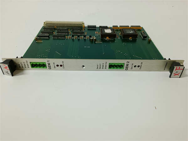
| Module Type | uGENI VME Interface |
| Channels | 2 (Serial 1 & 2) |
| Max Devices | 32 devices per channel (Daisy Chain) |
| Configuration | On-board DIP switches |
| Connection | Front-panel screw-type terminals |
| Sub-board Model | GNI2C1 (Typical) |
| Chip Version | 3.2 (Typical) |
| Mounting | VME Backplane (Card edge) |
Product Introduction
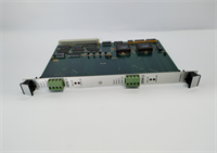
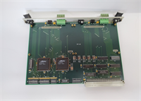
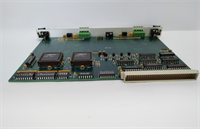
The GE HE700GEN200 is a VME interface module designed to connect GE Fanuc programmable logic controllers (PLCs) to Genius I/O networks. It installs directly into a VME rack, functioning as the Bus Controller (GBC) to manage data exchange between the CPU and field devices.This module features dual-channel architecture, allowing for redundant network paths or two independent networks from a single slot. It supports daisy-chaining up to 32 devices per channel. Configuration is hardware-based via on-board DIP switches, eliminating software overhead for basic setup.
HE700GEN200 GE
Installation & Configuration Guide
Preparation (10 min)
- Power Down: Disconnect power to the VME rack. Verify 0V potential at the chassis ground.
- Static Safety: Wear an ESD wrist strap connected to the rack’s unpainted metal. Static discharge can destroy the module instantly.
- Verify Hardware: Check the sub-board model; it should read
GNI2C1or similar. Ensure the chip version is 3.2 or higher.
Removal (5–10 min)
- Disconnect Cables: Unscrew the Genius bus cables from the front terminals (Serial 1/2).
- Eject: Loosen the captive screws at the top and bottom of the faceplate.
- Extract: Pull the card straight out. Do not wiggle it excessively; the backplane pins are fragile.
Installation (10 min)
- Slot Selection: Insert the module into the designated VME slot. Align the guide rails.
- Seat the Card: Push firmly until the backplane connector engages. Tighten the captive screws to secure the card.
- Wiring: Connect the Genius bus cable to the screw terminals.
- Serial 1: Primary network.
- Serial 2: Secondary/Redundant network.
- Shield: Connect cable shield to the shield terminal.
Power-On & Test (10 min)
- Termination: Verify the last device on the daisy chain has the termination resistor installed. The network must be terminated to prevent signal reflection.
- Power Up: Restore 24V DC power to the rack.
- DIP Check: Confirm DIP switch settings match your I/O map.
- Status LED: Watch the status LED. It should blink green (Run) or show specific fault codes if the network is open.
Troubleshooting Quick Reference
| Symptom | Probable Cause | Corrective Action |
|---|---|---|
| COMM FAIL Light ON | Open circuit in daisy chain | Check cable continuity between devices. Verify termination resistor is present at the end of the line. |
| No LEDs Lit | Backplane connection issue | Reseat the card. Check backplane pins for bending. Verify rack power supply voltage. |
| Intermittent Errors | Ground loop / Noise | Ensure the shield terminal is grounded. Check for “floating” grounds between the PLC and field devices. |
| Config Mismatch | Incorrect DIP switches | Compare physical switch positions against the hardware manual. Power cycle required after changes. |
Dimensions, Mounting & Wiring Notes
- Form Factor: Standard VME Bus Card (3U or 6U height, verify specific chassis compatibility).
- Mounting: Secured via top/bottom screws to the VME chassis rails.
- Terminals: Front-facing screw-type connectors.
- Wire Gauge: Typically 12-24 AWG (verify with manual).
- Torque: 4.5 lb-in (0.5 Nm) max. Do not overtighten; the plastic housing can crack.
FAQ
Can I use the HE700GEN200 to replace a single channel module?
Yes. You can use just Channel 1 and leave Channel 2 unconnected, or use it to split your I/O into two smaller networks. It is backward compatible with single-channel setups.What does the “C” in HE700GEN200C stand for?
It generally denotes the revision or specific hardware version of the module. It is functionally equivalent to the base HE700GEN200 but may have updated components or firmware.I’m getting noise interference on the Genius bus. What should I check?
Check your shielding first. The “Shield” terminal on the front panel must be connected to the cable shield. Also, ensure your power supply has a clean ground; dirty power often looks like communication errors on the Genius network.Is this module compatible with non-GE VME racks?
It is designed for GE Fanuc VME racks. While it fits standard VME backplanes, the logic mapping is specific to GE Series 90-70 or PACSystems architectures. It may not function in a generic VME chassis without specific GE CPU support.How do I configure the station address?
You use the DIP switches located on the faceplate or the internal sub-board (depending on the exact revision). Refer to the GNI2C1 manual for the specific binary switch settings for your station number.
GE HE700GEN200 VME Interface Module